|
|
|
PDF IR2011SPbF Data sheet ( Hoja de datos )
| Número de pieza | IR2011SPbF | |
| Descripción | HIGH AND LOW SIDE DRIVER | |
| Fabricantes | International Rectifier | |
| Logotipo | ||
Hay una vista previa y un enlace de descarga de IR2011SPbF (archivo pdf) en la parte inferior de esta página. Total 17 Páginas | ||
|
No Preview Available !
Data Sheet No.PD60217 Rev A
IR2011(S) & (PbF)
HIGH AND LOW SIDE DRIVER
Features
Product Summary
• Floating channel designed for bootstrap operation
Fully operational up to +200V
VOFFSET
200V max.
Tolerant to negative transient voltage, dV/dt immune
• Gate drive supply range from 10V to 20V
• Independent low and high side channels
• Input logicHIN/LIN active high
• Undervoltage lockout for both channels
• 3.3V and 5V input logic compatible
• CMOS Schmitt-triggered inputs with pull-down
• Matched propagation delay for both channels
• 8-Lead SOIC is also available LEAD-FREE (PbF)
IO+/-
VOUT
ton/off
Delay Matching
1.0A /1.0A typ.
10 - 20V
80 & 60 ns typ.
20 ns max.
Applications
• Audio Class D amplifiers
• High power DC-DC SMPS converters
• Other high frequency applications
Packages
Description
The IR2011 is a high power, high speed power MOSFET driver with independent high
and low side referenced output channels, ideal for Audio Class D and DC-DC converter
applications. Logic inputs are compatible with standard CMOS or LSTTL output, down
to 3.0V logic. The output drivers feature a high pulse current buffer stage designed for
minimum driver cross-conduction. Propagation delays are matched to simplify use in
high frequency applications. The floating channel can be used to drive an N-channel
power MOSFET in the high side configuration which operates up to 200 volts. Propri-
etary HVIC and latch immune CMOS technologies enable ruggedized monolithic con-
struction.
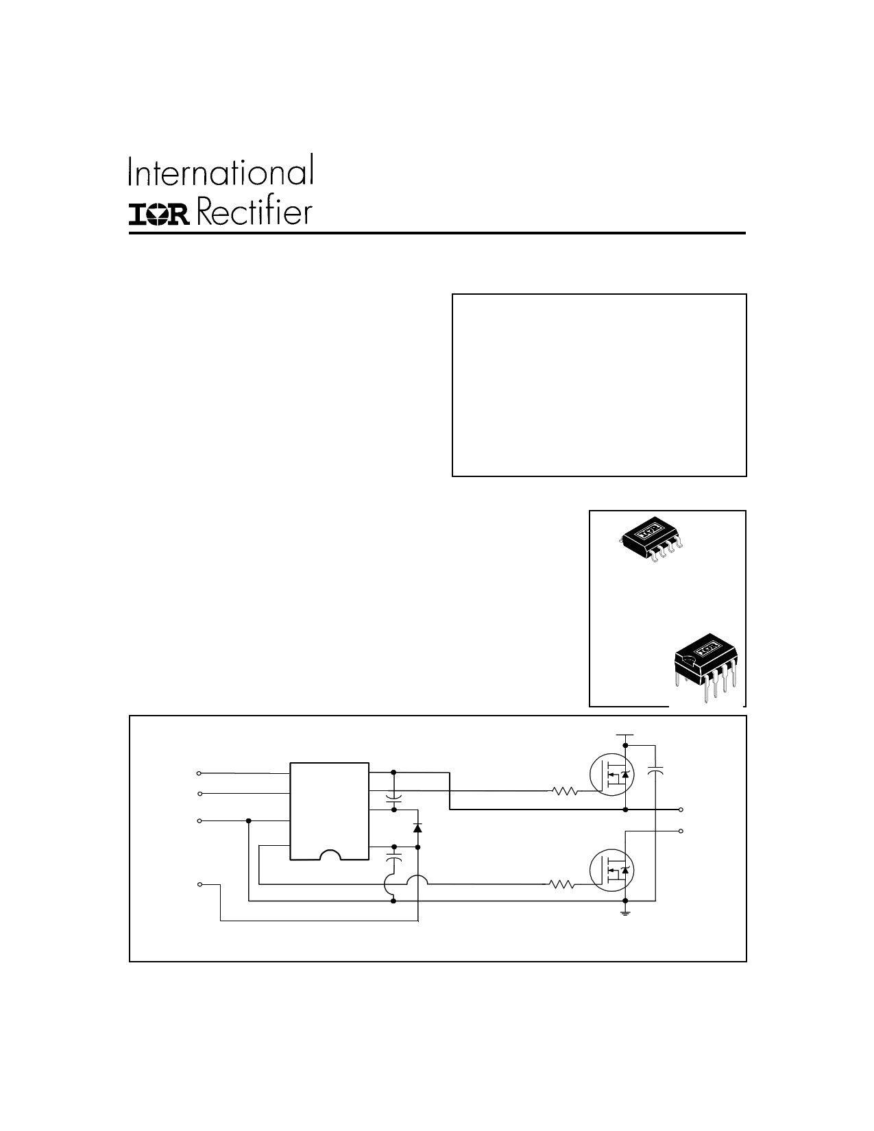
Typical Connection
8-Lead SOIC
IR2011S
also available
LEAD-FREE (PbF)
8-Lead PDIP
IR2011
200V
HIN
LIN
COM
5
HIN
LIN
COM
8 LO
VS 4
HO
VB
1
VCC
TO
LOAD
VCC
(Refer to Lead Assignments for correct configuration). This/These diagram(s) show electrical connections only. Please
refer to our Application Notes and DesignTips for proper circuit board layout.
www.irf.com
1
1 page 
IR2011(S) & (PbF)
50%
trise
90%
ton(H)
10%
DM1
ton(L)
10%
50%
HIN / LIN
tfall
90%
toff(H)
10%
HO
toff(L)
DM2
90%
LO
www.irf.com
Figure 1. Timing Diagram
5
5 Page 
IR2011(S) & (PbF)
500
400
300
200
100
M ax.
0
-50 -25
0 25 50 75 100 125
Temperature (oC)
Figure 12A. Offset Supply Leakage Current
vs. Temperature
500
400
300
200
100
0 M ax.
50 80
110 140 170
VB Boost Voltage (V)
200
600
500
400
300
200
100
0
-50
M ax.
Ty-p2. 5
0 25 50 75 100 125
Temperature (oC)
600
500
400
300
200
100
M ax.
0 Typ.
10 12 14 16 18
VBS Floating Supply Voltage (V)
20
www.irf.com
11
11 Page | ||
| Páginas | Total 17 Páginas | |
| PDF Descargar | [ Datasheet IR2011SPbF.PDF ] | |
Hoja de datos destacado
| Número de pieza | Descripción | Fabricantes |
| IR2011SPbF | HIGH AND LOW SIDE DRIVER | International Rectifier |
| Número de pieza | Descripción | Fabricantes |
| SLA6805M | High Voltage 3 phase Motor Driver IC. |
Sanken |
| SDC1742 | 12- and 14-Bit Hybrid Synchro / Resolver-to-Digital Converters. |
Analog Devices |
|
DataSheet.es es una pagina web que funciona como un repositorio de manuales o hoja de datos de muchos de los productos más populares, |
| DataSheet.es | 2020 | Privacy Policy | Contacto | Buscar |