|
|
|
PDF K847PH Data sheet ( Hoja de datos )
| Número de pieza | K847PH | |
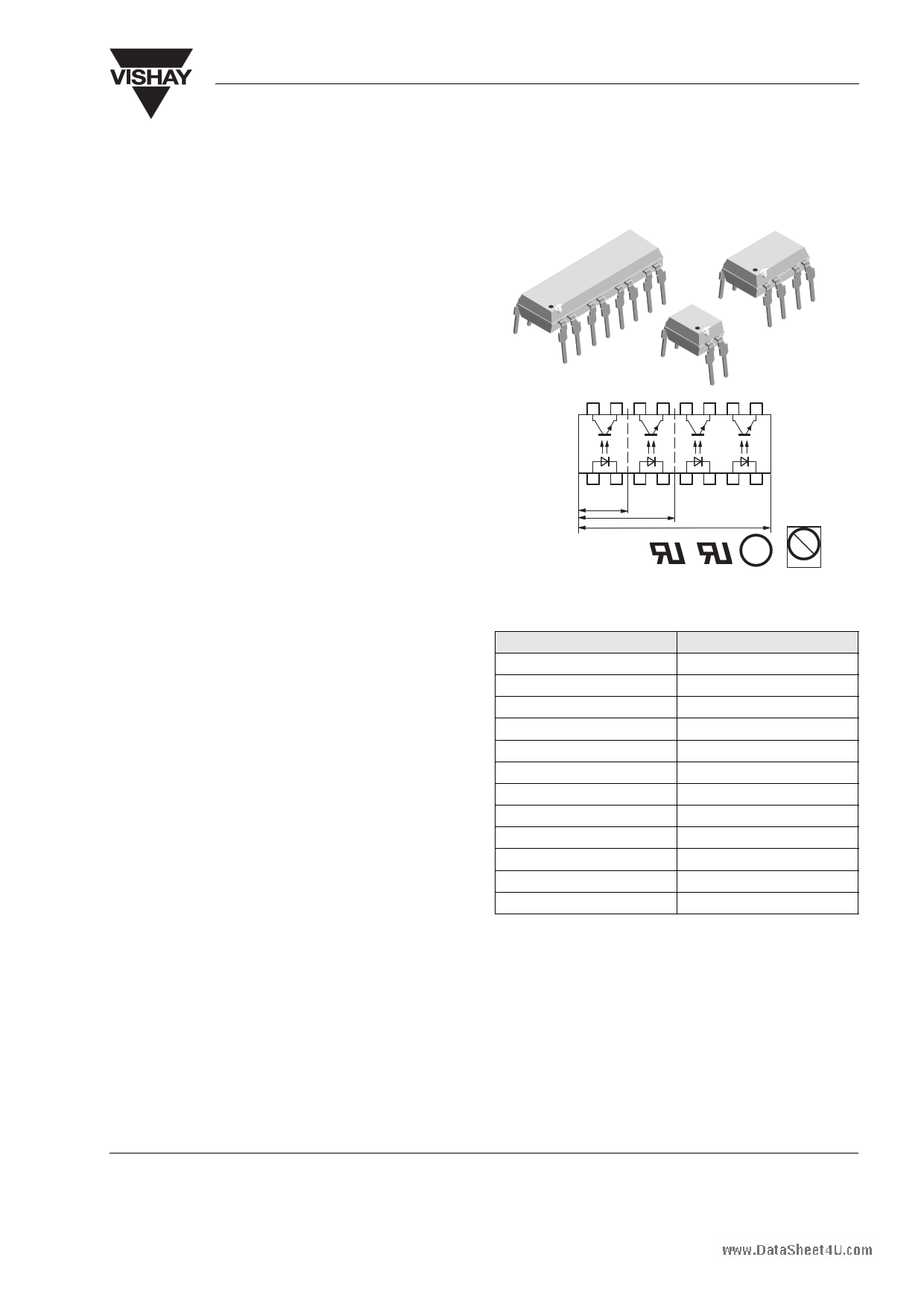
| Descripción | Optocoupler with Phototransistor Output | |
| Fabricantes | Vishay Telefunken | |
| Logotipo | ||
Hay una vista previa y un enlace de descarga de K847PH (archivo pdf) en la parte inferior de esta página. Total 9 Páginas | ||
|
No Preview Available !
www.DataSheet4U.com
K817P/ K827PH/ K847PH
Vishay Semiconductors
Optocoupler, Phototransistor Output
Features
• Endstackable to 2.54 mm (0.1") spacing
• DC isolation test voltage VISO = 5000 VRMS
• Low coupling capacitance of typical 0.3 pF
• Current Transfer Ratio (CTR) selected into groups
• Low temperature coefficient of CTR
• Wide ambient temperature range
• Available in single, dual and quad channel pack-
ages
• Lead-free component
• Component in accordance to RoHS 2002/95/EC
and WEEE 2002/96/EC
Agency Approvals
• UL1577, File No. E76222 System Code U, Double
Protection
• CSA 93751
CE
1
AC
4 PIN
8 PIN
17203_1
C
16 PIN
e3
Pb
Pb-free
Applications
Programmable logic controllers, modems, answering
machines, general applications
Description
In the K817P/ K827PH/ K847PH parts each channel
consist of a phototransistor optically coupled to a gal-
lium arsenide infrared-emitting diode in a 4-pin (sin-
gle); 8 pin (dual); 16-pin (quad) plastic dual inline
package.
The elements are mounted on one leadframe provid-
ing a fixed distance between input and output for high-
est safety requirements.
Order Information
K817P
K817P1
K817P2
K817P3
K817P4
K817P5
K817P6
K817P7
K817P8
K817P9
K827PH
K847PH
Part
Remarks
CTR 50 - 600 %, DIP-4
CTR 40 - 80 %, DIP-4
CTR 63 - 125 %, DIP-4
CTR 100 - 200 %, DIP-4
CTR 160 - 320 %, DIP-4
CTR 50 - 150 %, DIP-4
CTR 100 - 300 %, DIP-4
CTR 80 - 160 %, DIP-4
CTR 130 - 260 %, DIP-4
CTR 200 - 400 %, DIP-4
CTR 50 - 600 %, DIP-8
CTR 50 - 600 %, DIP-16
Document Number 83522
Rev. 1.7, 26-Oct-04
www.vishay.com
1
1 page 
www.DataSheet4U.com
K817P/ K827PH/ K847PH
Vishay Semiconductors
Typical Characteristics (Tamb = 25 °C unless otherwise specified)
300
Coupled device
250
200
Phototransistor
150
IR-diode
100
50
0
0
96 11700
40 80 120
Tamb – Ambient Temperature( °C )
Figure 4. Total Power Dissipation vs. Ambient Temperature
10000
1000
VCE = 20 V
IF = 0
100
10
1
0
95 11026
25 50 75 100
Tamb - Ambient Temperature ( ° C )
Figure 7. Collector Dark Current vs. Ambient Temperature
1000
100
10
1
0.1
0 0.2 0.4 0.6 0.8 1.0 1.2 1.4 1.6 1.8 2.0
96 11862
VF - Forward Voltage ( V )
Figure 5. Forward Current vs. Forward Voltage
100
VCE=5V
10
1
0.1
0.01
0.1
95 11027
1 10
IF – Forward Current ( mA )
100
Figure 8. Collector Current vs. Forward Current
2.0
VCE=5V
IF=5mA
1.5
1.0
0.5
0
–25
95 11025
0 25 50 75
Tamb – Ambient Temperature ( °C )
Figure 6. Relative Current Transfer Ratio vs. Ambient
Temperature
100
20mA
IF=50mA
10 10mA
5mA
1 2mA
1mA
0.1
0.1
95 10985
1 10 100
VCE – Collector Emitter Voltage ( V )
Figure 9. Collector Current vs. Collector Emitter Voltage
Document Number 83522
Rev. 1.7, 26-Oct-04
www.vishay.com
5
5 Page | ||
| Páginas | Total 9 Páginas | |
| PDF Descargar | [ Datasheet K847PH.PDF ] | |
Hoja de datos destacado
| Número de pieza | Descripción | Fabricantes |
| K847PH | Optocoupler with Phototransistor Output | Vishay Telefunken |
| Número de pieza | Descripción | Fabricantes |
| SLA6805M | High Voltage 3 phase Motor Driver IC. |
Sanken |
| SDC1742 | 12- and 14-Bit Hybrid Synchro / Resolver-to-Digital Converters. |
Analog Devices |
|
DataSheet.es es una pagina web que funciona como un repositorio de manuales o hoja de datos de muchos de los productos más populares, |
| DataSheet.es | 2020 | Privacy Policy | Contacto | Buscar |