|
|
|
PDF S3842 Data sheet ( Hoja de datos )
| Número de pieza | S3842 | |
| Descripción | Current Mode PWM Controller | |
| Fabricantes | AUK corp | |
| Logotipo | ||
Hay una vista previa y un enlace de descarga de S3842 (archivo pdf) en la parte inferior de esta página. Total 8 Páginas | ||
|
No Preview Available !
Semiconductor
S3842
Current Mode PWM Controller
Descriptions
The S3842, high performance current mode controller, Provides the necessary features to
off-line and DC-DC fixed frequency current control applications offering the designer a cost
effective solution with minimal external components. Internally protection circuity includes
built-in input and reference under-voltage lockout and current limiting with hysteresis.
Also other characteristics of internal circuit provide improved line regulation, enhanced load
response, trimmed oscillation for precise duty cycle control, a temperature compensated
reference, high gain error amplifier, current sensing comparator and totempole output
designed to source and sink high peak current from a capacitive load such as the gate of a
power MOSFET.
Features
• Optimized for off-line control
• Current mode operation to 500 ㎑
• Low start up and operating current • Under voltage lockout with 6V hysteresis
• Pulse by pulse current limiting
• Internally trimmed bandgap reference about 5V
• Enhanced load response characteristic • Automatic feed forward compensation
Ordering Information
Type NO.
Marking
S3842
S3842
Package Code
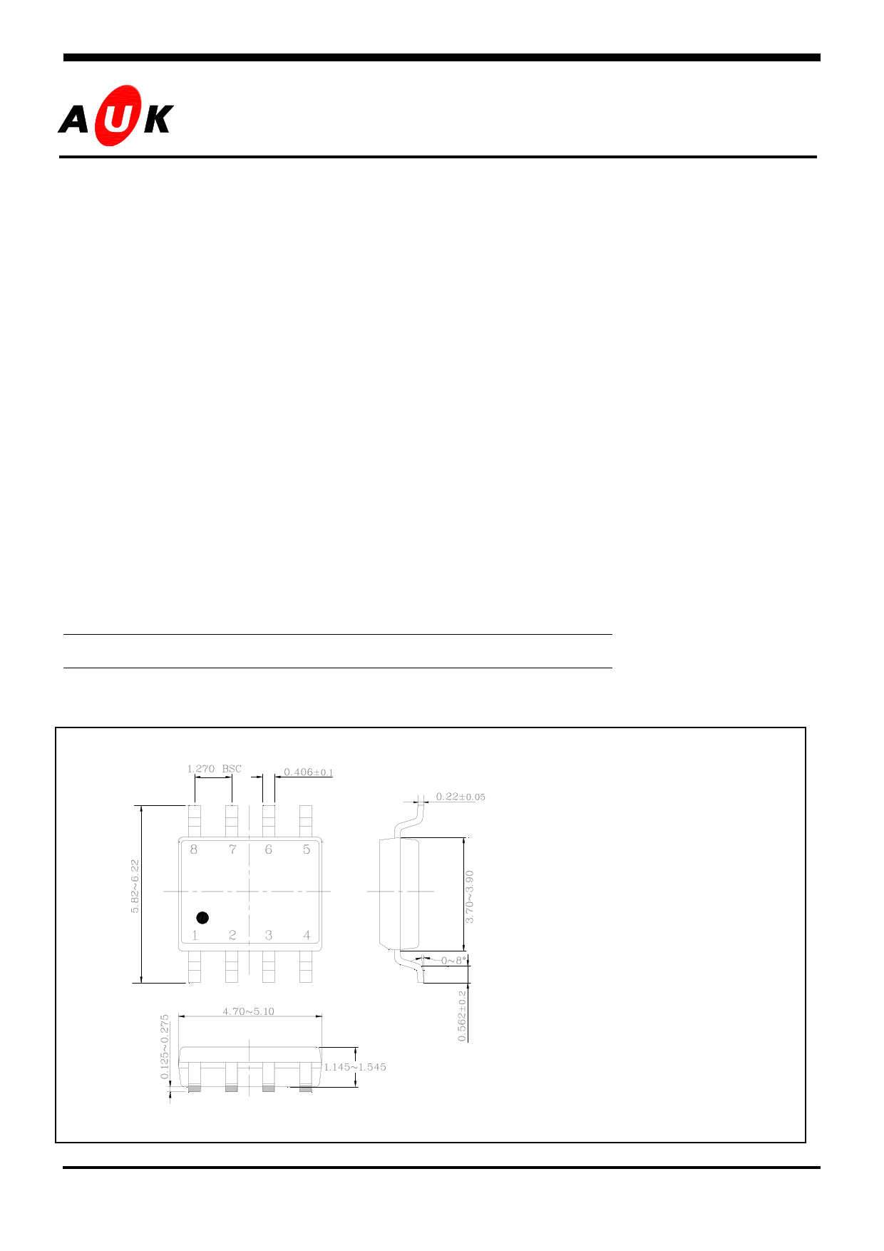
SOP-8
Outline Dimensions
unit : mm
PIN Connections
1. Output / Compensation
2. Voltage feedback. Input
3. Current sense Input
4. Rt/Ct
5. GND
6. Output
7. Vcc
8. Vref
KSI-8006-003
1
1 page 
S3842
2. Oscillator Waveforms and Maximum Duty Cycle
The oscillator frequency is programmed by the values
LARGE Rt
SMALL Ct
8
Rt
4
SMALL Rt
LARGE Ct
Ct
5
Vpin4
INTERNAL
CLOCK
Vpin4
selected for the timing components Rt and Ct. Ct is
charged from 5V, Vref, through resistor Rt to
approximately 2.8V and discharged to 1.2V by an
internal current sink.
During the discharge of Ct, the oscillator generates an
internal blanking pulse and the center input NOR gate high.
This makes output to be in a low state and control the
INTERNAL
CLOCK
amount of output dead time.
3. Error AMP Configuration
2.50V
+
Vin
Zt 2 -
Error amp output(Pin1) is provided for external loop
0.5mA Compensation and error amp can source or sink up to 0.5mA.
The non-inverting input is internally biased at 2.5V and is
not pinned out. The converter output voltage is typically
divided down and monitored by the inverting input(pin2).
COMP
Zf 1
4. Current Sense Circuit
Iβ
R(V pin1 - 2V be)
Ipeak =
3R x Rs
R
C
Rs
ERROR
AMP
2R
R IV
1
COMP
3
CURRENT
SENSE
GND
5
A normal operating conditions occurs when the power supply output is overloaded or if output voltage to 1.0V
Therefore the maximum peak switch current is lpk(max)=1.0V/Rs, and under the normal operating conditions the
peak inductor current controlled by the voltage at pin1.
KSI-8006-003
5
5 Page | ||
| Páginas | Total 8 Páginas | |
| PDF Descargar | [ Datasheet S3842.PDF ] | |
Hoja de datos destacado
| Número de pieza | Descripción | Fabricantes |
| S3842 | Current Mode PWM Controller | AUK corp |
| S3842P | Current Mode PWM Controller | AUK corp |
| S3843 | Current Mode PWM Controller | AUK corp |
| S3843P | Current Mode PWM Controller | AUK corp |
| Número de pieza | Descripción | Fabricantes |
| SLA6805M | High Voltage 3 phase Motor Driver IC. |
Sanken |
| SDC1742 | 12- and 14-Bit Hybrid Synchro / Resolver-to-Digital Converters. |
Analog Devices |
|
DataSheet.es es una pagina web que funciona como un repositorio de manuales o hoja de datos de muchos de los productos más populares, |
| DataSheet.es | 2020 | Privacy Policy | Contacto | Buscar |