|
|
|
PDF INA115 Data sheet ( Hoja de datos )
| Número de pieza | INA115 | |
| Descripción | Precision INSTRUMENTATION AMPLIFIER | |
| Fabricantes | Burr-Brown Corporation | |
| Logotipo | ||
Hay una vista previa y un enlace de descarga de INA115 (archivo pdf) en la parte inferior de esta página. Total 11 Páginas | ||
|
No Preview Available !
®
INA115
INA115
Precision
INSTRUMENTATION AMPLIFIER
FEATURES
q LOW OFFSET VOLTAGE: 50µV max
q LOW DRIFT: 0.25µV/°C max
q LOW INPUT BIAS CURRENT: 2nA max
q HIGH COMMON-MODE REJECTION:
115dB min
q INPUT OVER-VOLTAGE PROTECTION:
±40V
q WIDE SUPPLY RANGE: ±2.25 TO ±18V
q LOW QUIESCENT CURRENT: 3mA max
q SOL-16 SURFACE-MOUNT PACKAGE
APPLICATIONS
q SWITCHED-GAIN AMPLIFIER
q BRIDGE AMPLIFIER
q THERMOCOUPLE AMPLIFIER
q RTD SENSOR AMPLIFIER
q MEDICAL INSTRUMENTATION
q DATA ACQUISITION
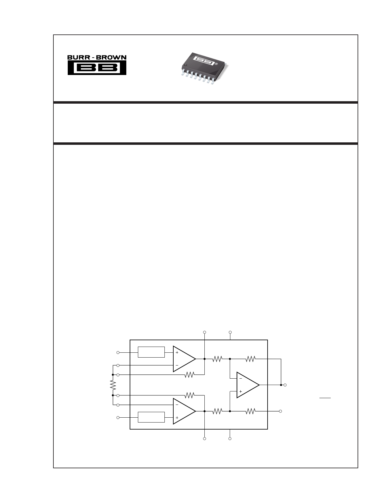
DESCRIPTION
The INA115 is a low cost, general purpose instrumen-
tation amplifier offering excellent accuracy. Its versa-
tile three-op amp design and small size make it ideal
for a wide range of applications. Similar to the model
INA114, the INA115 provides additional connections
to the input op amps, A1 and A2, which improve gain
accuracy in high gains and are useful in forming
switched-gain amplifiers.
A single external resistor sets any gain from 1 to
10,000. Internal input protection can withstand up to
±40V without damage.
The INA115 is laser trimmed for very low offset
voltage (50µV), drift (0.25µV/˚C) and high common-
mode rejection (115dB at G=1000). It operates with
power supplies as low as ±2.25V, allowing use in
battery operated and single 5V supply systems. Quies-
cent current is 3mA maximum.
The INA115 is available in the SOL-16 surface-mount
package, specified for the –40°C to +85°C tempera-
ture range.
VO1 V+
1 13
– 4 Over-Voltage
VIN Protection
2
3
A1
25kΩ
INA115
25kΩ
25kΩ
Feedback
12
RG
14
15
+5
VIN
Over-Voltage
Protection
25kΩ
A2
25kΩ
A3
25kΩ
11 VO
Ref
10
G = 1 + 50kΩ
RG
87
VO2 V–
International Airport Industrial Park • Mailing Address: PO Box 11400, Tucson, AZ 85734 • Street Address: 6730 S. Tucson Blvd., Tucson, AZ 85706 • Tel: (520) 746-1111 • Twx: 910-952-1111
Internet: http://www.burr-brown.com/ • FAXLine: (800) 548-6133 (US/Canada Only) • Cable: BBRCORP • Telex: 066-6491 • FAX: (520) 889-1510 • Immediate Product Info: (800) 548-6132
©1992 Burr-Brown Corporation
PDS-1169B
Printed in U.S.A. October, 1993
1 page 
TYPICAL PERFORMANCE CURVES (CONT)
At TA = +25°C, VS = ±15V, unless otherwise noted.
1200
1000
800
600
400
200
0
1
SETTLING TIME vs GAIN
0.01%
0.1%
10 100
Gain (V/V)
1000
6
4
2
0
–2
–4
–6
0
OFFSET VOLTAGE WARM-UP vs TIME
G >100
15 30 45 60 75 90 105 120
Time from Power Supply Turn-on (s)
INPUT BIAS AND INPUT OFFSET CURRENT
vs TEMPERATURE
2
1
±IB
0
IOS
–1
–2
–40
–15 10
35
Temperature (°C)
60
85
INPUT BIAS CURRENT
vs COMMON-MODE INPUT VOLTAGE
3
Both Inputs
2 |Ib1| + |Ib2|
One Input
1
0
Over-Voltage
Protection
–1
Normal
Operation
Over-Voltage
Protection
–2 One Input
–3
–45
Both Inputs
–30 –15
0
15
Common-Mode Voltage (V)
30
45
INPUT BIAS CURRENT
vs DIFFERENTIAL INPUT VOLTAGE
3
2
1
0
–1 G = 1
–2
–3
–45
G = 10
G = 100
G = 1000
–30 –15
0
15 30
Differential Overload Voltage (V)
45
32
28
24
20
16
12
8
4
0
10
MAXIMUM OUTPUT SWING vs FREQUENCY
G = 1, 10
G = 100
G = 1000
100 1k 10k 100k
Frequency (Hz)
1M
®
5 INA115
5 Page 
INPUT COMMON-MODE RANGE
The linear common-mode range of the input op amps of the
INA115 is approximately ±13.75V (or 1.25V from the power
supplies). As the output voltage increases, however, the linear
input range will be limited by the output voltage swing of the
input amplifiers, A1 and A2. The common-mode range is
related to the output voltage of the complete amplifier—see
performance curve “Input Common-Mode Range vs Output
Voltage.”
A combination of common-mode and differential input sig-
nals can cause the output of A or A to saturate. Figure 6
12
shows the output voltage swing of A1 and A2 expressed in
terms of a common-mode and differential input voltages.
Output swing capability of the input amplifiers, A1 and A2 is
the same as the output amplifier, A . For applications where
3
input common-mode range must be maximized, limit the
output voltage swing by connecting the INA115 in a lower
gain (see performance curve “Input Common-Mode Voltage
Range vs Output Voltage”). If necessary, add gain after the
INA115 to increase the voltage swing.
Input-overload often produces an output voltage that appears
normal. For example, an input voltage of +20V on one input
and +40V on the other input will obviously exceed the linear
common-mode range of both input amplifiers. Since both
input amplifiers are saturated to the nearly the same output
voltage limit, the difference voltage measured by the output
amplifier will be near zero. The output of the INA115 will be
near 0V even though both inputs are overloaded.
INPUT PROTECTION
The inputs of the INA115 are individually protected for
voltages up to ±40V. For example, a condition of –40V on one
input and +40V on the other input will not cause damage.
Internal circuitry on each input provides low series impedance
under normal signal conditions. To provide equivalent protec-
tion, series input resistors would contribute excessive noise. If
the input is overloaded, the protection circuitry limits the input
current to a safe value (approximately 1.5mA). The typical
performance curve “Input Bias Current vs Common-Mode
Input Voltage” shows this input current limit behavior. The
inputs are protected even if the power supply voltage is zero.
OTHER APPLICATIONS
See the INA114 data sheet for other applications circuits of
general interest.
VCM –
G • VD
2
Over-Voltage
Protection
A1
VD
2
25kΩ
RG
VD
2
VCM
Over-Voltage
Protection
25kΩ
A2
VCM +
G • VD
2
FIGURE 6. Voltage Swing of A1 and A2.
25kΩ
25kΩ
V+
INA115
25kΩ
A3
G = 1 + 50kΩ
RG
VO = G • VD
25kΩ
V–
LA
RA
RL
390kΩ
FIGURE 7. ECG Amplifier with Right Leg Drive.
390kΩ
OPA177
11
VO1
RG INA115
VO2
24.9kΩ
24.9kΩ
VO
INA115
®
11 Page | ||
| Páginas | Total 11 Páginas | |
| PDF Descargar | [ Datasheet INA115.PDF ] | |
Hoja de datos destacado
| Número de pieza | Descripción | Fabricantes |
| INA110 | Fast-Settling FET-Input INSTRUMENTATION AMPLIFIER | Burr-Brown Corporation |
| INA110 | Fast-Settling FET-Input Instrumentation Amp (Rev. A) | Texas Instruments |
| INA110AG | Fast-Settling FET-Input INSTRUMENTATION AMPLIFIER | Burr-Brown Corporation |
| INA110BG | Fast-Settling FET-Input INSTRUMENTATION AMPLIFIER | Burr-Brown Corporation |
| Número de pieza | Descripción | Fabricantes |
| SLA6805M | High Voltage 3 phase Motor Driver IC. |
Sanken |
| SDC1742 | 12- and 14-Bit Hybrid Synchro / Resolver-to-Digital Converters. |
Analog Devices |
|
DataSheet.es es una pagina web que funciona como un repositorio de manuales o hoja de datos de muchos de los productos más populares, |
| DataSheet.es | 2020 | Privacy Policy | Contacto | Buscar |