|
|
|
PDF EL7581 Data sheet ( Hoja de datos )
| Número de pieza | EL7581 | |
| Descripción | 3-Channel DC-DC Converter | |
| Fabricantes | Intersil Corporation | |
| Logotipo | ||
Hay una vista previa y un enlace de descarga de EL7581 (archivo pdf) en la parte inferior de esta página. Total 17 Páginas | ||
|
No Preview Available !
®
Data Sheet
April 16, 2004
EL7581
FN7100.4
3-Channel DC-DC Converter
The EL7581 is a 3-channel DC-DC
converter IC which is designed
primarily for use in TFT/LCD
applications. It features a PWM boost converter with 2.7V to
14V input capability and 5V to 17V output, which powers the
column drivers and provides up to 720mA @12V, 570mA @
15V from 5V input. A pair of charge pump control circuits
provide regulated outputs of VON and VOFF supplies at 8V
to 40V and -5V to -40V, respectively, each at up to 60mA.
The EL7581 features adjustable switching frequency,
adjustable soft start, and a separate output VON enable
control to allow selection of supply start-up sequence. An
over-temperature feature is provided to allow the IC to be
automatically protected from excessive power dissipation.
The EL7581 is available in a 20-pin HTSSOP package and
is specified for operation over the full -40°C to +85°C
temperature range.
Ordering Information
PART
NUMBER
PACKAGE
TAPE &
REEL PKG. DWG. #
EL7581IRE
20-Pin HTSSOP
-
MDP0048
EL7581IRE-T7
20-Pin HTSSOP
7”
MDP0048
EL7581IRE-T13 20-Pin HTSSOP
13”
MDP0048
EL7581IREZ
(Note)
20-Pin HTSSOP
(Pb-Free)
-
MDP0048
EL7581IREZ-T7 20-Pin HTSSOP
(Note)
(Pb-Free)
7”
MDP0048
EL7581IREZ-T13 20-Pin HTSSOP
(Note)
(Pb-Free)
13”
MDP0048
NOTE: Intersil Pb-Free products employ special Pb-free material
sets; molding compounds/die attach materials and 100% matte tin
plate termination finish, which is compatible with both SnPb and Pb-
free soldering operations. Intersil Pb-Free products are MSL
classified at Pb-free peak reflow temperatures that meet or exceed
the Pb-free requirements of IPC/JEDEC J Std-020B.
Features
• TFT/LCD display supply
- Boost regulator
- VON charge pump
- VOFF charge pump
• 2.7V to 14V VIN supply
• 5V < VBOOST < 17V
• 5V < VON < 40V
• -40V < VOFF < 0V
• VBOOST = 12V @ 720mA
• VBOOST = 15V @ 570mA
• High frequency, small inductor DC-DC boost circuit
• Over 90% efficient DC-DC boost converter capability
• Adjustable frequency
• Adjustable soft-start
• Adjustable outputs
• Small parts count
Applications
• TFT-LCD panels
• PDAs
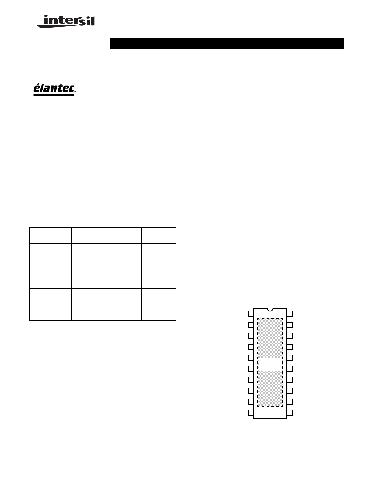
Pinout
EL7581
(20-PIN HTSSOP)
TOP VIEW
VSSB 1
20 ROSC
SS 2
19 ENP
FBB 3
18 ENBN
VDDB 4
17 VREF
LX 5
LX 6
THERMAL
PAD*
16 PGND
15 PGND
LX 7
14 DRVP
DRVN 8
13 VDDP
VDDN 9
12 FBP
FBN 10
11 VSSP
*Refer to PCB layout guideline.
1
CAUTION: These devices are sensitive to electrostatic discharge; follow proper IC Handling Procedures.
1-888-INTERSIL or 321-724-7143 | Intersil (and design) is a registered trademark of Intersil Americas Inc.
Copyright © Intersil Americas Inc. 2004. All Rights Reserved. Elantec is a registered trademark of Elantec Semiconductor, Inc.
All other trademarks mentioned are the property of their respective owners.
1 page 
EL7581
Typical Performance Curves
95
9V
90
85
12V
15V
80
75
70
65 VIN = 5V
FS = 1MHz
60
0 200 400 600 800
IOUT (mA)
FIGURE 1. EFFICIENCY vs IOUT
1K
95
90 5V
85 9V
80 15V 12V
75
70
65 VIN = 3.3V
FS = 700kHz
60
0 200 400 600 800
IOUT (mA)
FIGURE 2. EFFICIENCY vs IOUT
1K
95
9V
90
12V
85 15V
80
75
70
65 VIN = 5V
FS = 700kHz
60
0 200 400 600 800
IOUT (mA)
FIGURE 3. EFFICIENCY vs IOUT
1K
2
1.5
1
0.5
0
-0.5
-1
-1.5
-2
50
VIN = 3.3V
FS = 1MHz
15V
12V
9V
5V
250 450 650 850
IOUT (mA)
FIGURE 5. LOAD REGULATION
1050
95
90
5V
85
9V
80 15V 12V
75
70
65 VIN = 3.3V
FS = 1MHz
60
0 200 400 600 800
IOUT (mA)
FIGURE 4. EFFICIENCY vs IOUT
1K
3
2.5
2
1.5
1
0.5
0
-0.5
-1
-1.5
50
VIN = 5V
FS = 1MHz
9V
15V 12V
250 450 650 850
IOUT (mA)
FIGURE 6. LOAD REGULATION
1050
5
5 Page 
EL7581
Applications Information
The EL7581 is high efficiency multiple output power solution
designed specifically for thin-film transistor (TFT) liquid
crystal display (LCD) applications. The device contains one
high current boost converter and two low power charge
pumps (VON and VOFF).
The boost converter contains an integrated N-channel
MOSFET to minimize the number of external components.
The converter output voltage can be set from 5V to 18V with
external resistors. The VON and VOFF charge pumps are
independently regulated to positive and negative voltages
using external resistors. Output voltages as high as 40V can
be achieved with additional capacitors and diodes.
Boost Converter
The boost converter operates in constant frequency pulse-
width-modulation (PWM) mode. Quiescent current for the
EL7581 is only 5mA when enabled, and since only the low
side MOSFET is used, switch drive current is minimized.
90% efficiency is achieved in most common application
operating conditions.
A functional block diagram with typical circuit configuration is
shown on the previous page. Regulation is performed by the
PWM comparator which regulates the output voltage by
comparing a divided output voltage with an internal
reference voltage. The PWM comparator outputs its result to
the PWM logic. The PWM logic switches the MOSFET on
and off through the gate drive circuit. Its switching frequency
is external adjustable with a resistor from timing control pin
(ROSC) to ground. The boost converter has 200kHz to
1.2MHz operating frequency range.
Start-Up
After VDDB reaches a threshold of about 2V, the power
MOSFET is controlled by the start-up oscillator, which
generates fixed duty-ratio of 0.5 - 0.7 at a frequency of
several hundred kilohertz. This will boost the output voltage,
providing the initial output current load is not too great
(<250mA).
When VDDB reaches about 3.7V, the PWM comparator
takes over the control. The duty ratio will be decided by the
multiple-input direct summing comparator, Max_Duty signal
(about 90% duty-ratio), and the Current Limit Comparator,
whichever is the smallest.
The soft-start is provided by the current limit comparator. As
the internal 12µA current source charges the external soft-
start capacitor, the peak MOSFET current is limited by the
voltage on the capacitor. This in turn controls the rising rate
of output voltage.
The regulator goes through the start-up sequence as well
after the ENBN signal is pulled to HI.
Steady-State Operation
When the output reaches the preset voltage, the regulator
operates at steady state. Depending on the input/output
condition and component, the inductor operates at either
continuous-conduction mode or discontinuous-conduction
mode.
In the continuous-conduction mode, the inductor current is a
triangular waveform and LX voltage a pulse waveform. In the
discontinuous-conduction mode, the inductor current is
completely ‘dried-out’ before the MOSFET is turned on
again. The input voltage source, the inductor, and the
MOSFET and output diode parasitic capacitors forms a
resonant circuit. Oscillation will occur in this period. This
oscillation is normal and will not affect the regulation.
At very low load, the MOSFET will skip pulse sometimes.
This is normal.
Current Limit
The MOSFET current limit is nominal ILMT = 2.75A. This
restricts the maximum output current IOMAX based on the
following formula:
IOMAX
=
IL
M
T
–
∆---2--L-
× -VV----I-O-N--
where:
• ∆IL is the inductor peak-to-peak current ripple and is
decided by:
∆IL = -V---L-I--N-- × -F-D--S--
• D is the MOSFET turn-on radio and is decided by:
D = -V----O----V-----O--V----I--N--
• FS is the switching frequency.
The following table gives typical values:
(Margins are considered in deriving IOMAX. They are 10%,
3%, 20%, 10%, and 20% on VIN, VO, L, FS, and ILMT,
respectively.)
TABLE 1. MAXIMUM CONTINUOUS OUTPUT CURRENT
VIN (V)
3.3
VO (V)
5
L (µH)
10
FS (kHz) IOMAX (mA)
1000
1200
3.3
9
10
1000
660
3.3
12
10
1000
490
3.3
15
10
1000
390
5
9
10
1000
980
5
12
10
1000
720
5
15
10
1000
570
12
15
10
1000
1300
12
18
10
1000
1100
11
11 Page | ||
| Páginas | Total 17 Páginas | |
| PDF Descargar | [ Datasheet EL7581.PDF ] | |
Hoja de datos destacado
| Número de pieza | Descripción | Fabricantes |
| EL7581 | 3-Channel DC-DC Converter | Intersil Corporation |
| EL7583 | 3-Channel DC-DC Converter | Intersil Corporation |
| EL7585 | TFT-LCD Power Supply | Intersil Corporation |
| EL7585A | TFT-LCD Power Supply | Intersil Corporation |
| Número de pieza | Descripción | Fabricantes |
| SLA6805M | High Voltage 3 phase Motor Driver IC. |
Sanken |
| SDC1742 | 12- and 14-Bit Hybrid Synchro / Resolver-to-Digital Converters. |
Analog Devices |
|
DataSheet.es es una pagina web que funciona como un repositorio de manuales o hoja de datos de muchos de los productos más populares, |
| DataSheet.es | 2020 | Privacy Policy | Contacto | Buscar |