|
|
|
PDF EL7515 Data sheet ( Hoja de datos )
| Número de pieza | EL7515 | |
| Descripción | High Frequency PWM Step-Up Regulator | |
| Fabricantes | Intersil Corporation | |
| Logotipo | ||
Hay una vista previa y un enlace de descarga de EL7515 (archivo pdf) en la parte inferior de esta página. Total 8 Páginas | ||
|
No Preview Available !
®
Data Sheet
July 2, 2003
EL7515
FN7120
High Frequency PWM Step-Up Regulator
The EL7515 is a high frequency, high
efficiency step-up DC:DC regulator
operated at fixed frequency PWM
mode. With an integrated 1.4A MOSFET, it can deliver up to
600mA output current at up to 92% efficiency. The
adjustable switching frequency is up to 1.2MHz, making it
ideal for DSL applications.
When shut down, it draws <1µA of current. This feature,
along with the minimum starting voltage of 1.8V, makes it
suitable for portable equipment powered by one lithium ion,
3 to 4 NiMH cells, or 2 cells of alkaline battery.
The EL7515 is available in a 10-pin MSOP package, with
maximum height of 1.1mm. With proper external
components, the whole converter takes less than 0.25in2
PCB space.
This device is specified for operation over the full -40°C to
+85°C temperature range.
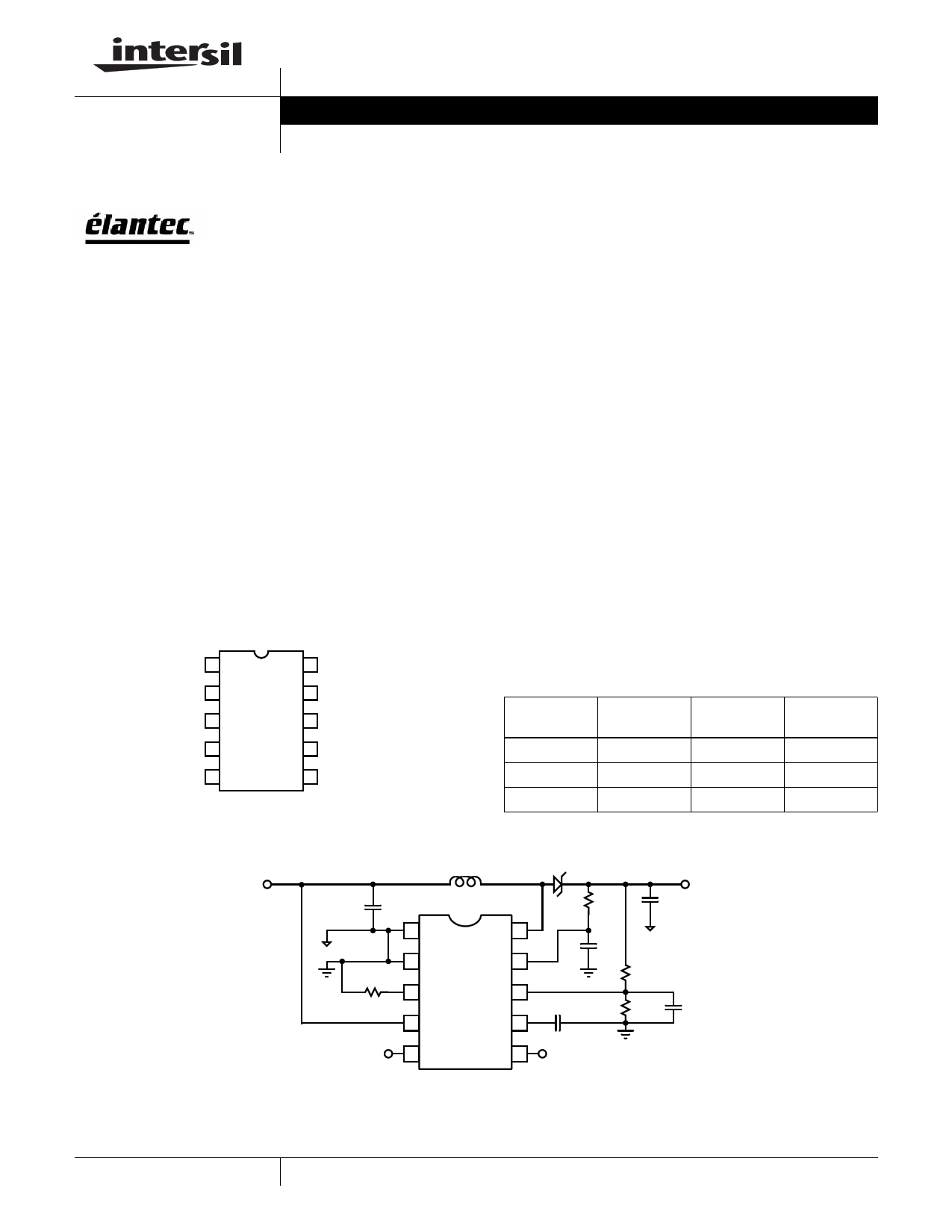
Pinout
EL7515
(10-PIN MSOP)
TOP VIEW
PGND 1
SGND 2
RT 3
EN 4
LBI 5
10 LX
9 VDD
8 FB
7 SS
6 LBO
Features
• Up to 92% efficiency
• Up to 600mA IOUT
• 4.5V < VOUT < 17V
• 1.8V < VIN < 13.2V
• Up to 1.2MHz adjustable frequency
• <1µA shutdown current
• Adjustable soft-start
• Low battery detection
• Internal thermal protection
• 1.1mm max height 10-pin MSOP package
Applications
• 3V to 5V and 12V converters
• 5V to 12V converters
• TFT-LCD
• DSL
• Portable equipment
• Desktop equipment
Ordering Information
PART
NUMBER
EL7515IY
EL7515IY-T7
EL7515IY-T13
PACKAGE TAPE & REEL PKG. DWG. #
10-Pin MSOP
-
MDP0043
10-Pin MSOP
7”
MDP0043
10-Pin MSOP
13”
MDP0043
Typical Application
VIN
(1.8V-9V)
L1
C1
10µF
10µH
1 PGND
LX 10
R3
100kΩ
2 SGND
3 RT
4 EN
VDD 9
FB 8
SS 7
5 LBI
LBO 6
D1
C3
20nF
R4
1.4kΩ
C5
22µF
VOUT
(12V UP TO
630mA)
C4
0.1µF
R2
82kΩ
R1
10kΩ
C10
4.7nF
1
CAUTION: These devices are sensitive to electrostatic discharge; follow proper IC Handling Procedures.
1-888-INTERSIL or 321-724-7143 | Intersil (and design) is a registered trademark of Intersil Americas Inc.
Copyright © Intersil Americas Inc. 2003. All Rights Reserved. Elantec is a registered trademark of Elantec Semiconductor, Inc.
All other trademarks mentioned are the property of their respective owners.
1 page 
Typical Performance Curves (Continued)
EL7515
VIN=5V, VO=12V, IO=30mA
∆VIN
VLX
50mV/DIV
10V/DIV
∆VO
IL
20mV/DIV
0.5A/DIV
0.5µs/DIV
FIGURE 7. STEADY STATE OPERATION (INDUCTOR
DISCONTINUOUS CONDUCTION)
VIN=5V, VO=12V, IO=300mA
∆VIN
VLX
∆VO
IL
50mV/DIV
10V/DIV
20mV/DIV
0.5A/DIV
0.5µs/DIV
FIGURE 8. STEADY STATE OPERATION (INDUCTOR
CONTINUOUS CONDUCTION)
VIN=5V, VO=12V, IO=300mA
∆VIN
VO
IL
0.5ms/DIV
FIGURE 9. POWER-UP
2V/DIV
5V/DIV
0.5A/DIV
Applications Information
The EL7515 is a step-up regulator, operated at fixed
frequency pulse-width-modulation (PWM) control. The input
voltage is 1.8V - 13.2V and output voltage is 4.5V - 17V. The
switching frequency (up to 1.2MHz) is decided by the
resistor connected to RT pin.
Start-Up
After VDD reaches a threshold of about 1.7V, the start-up
oscillator generates fixed duty-ratio of 0.5 - 0.7 at a
frequency of several hundred kilohertz. This will boost the
output voltage.
When VDD reaches about 3.7V, the PWM comparator takes
over the control. The duty ratio will be decided by the
multiple-input direct summing comparator, Max_Duty signal
(about 90% duty-ratio), and the Current Limit Comparator,
whichever is the smallest.
The soft-start is provided by the current limit comparator. As
the internal 12µA current source charges the external CSS,
the peak MOSFET current is limited by the voltage on the
5
VIN=5V, VO=12V, IO=50mA TO 300mA
IO
∆VO
100mA/DIV
0.5V/DIV
0.2ms/DIV
FIGURE 10. LOAD TRANSIENT RESPONSE
capacitor. This in turn controls the rising rate of the output
voltage.
The regulator goes through the start-up sequence as well
after the EN signal is pulled to HI.
Steady-State Operation
When the output reaches the preset voltage, the regulator
operates at steady state. Depending on the input/output
conditions and component values, the inductor operates at
either continuous-conduction mode or discontinuous-
conduction mode.
In the continuous-conduction mode, the inductor current is a
triangular waveform and LX voltage a pulse waveform. In the
discontinuous-conduction mode, the inductor current is
completely dried out before the MOSFET is turned on again.
The input voltage source, the inductor, and the MOSFET and
output diode parasitic capacitors forms a resonant circuit.
Oscillation will occur in this period. This oscillation is normal
and will not affect the regulation.
5 Page | ||
| Páginas | Total 8 Páginas | |
| PDF Descargar | [ Datasheet EL7515.PDF ] | |
Hoja de datos destacado
| Número de pieza | Descripción | Fabricantes |
| EL7512 | High Frequency PWM Step-Up Regulator | Intersil Corporation |
| EL7512C | High Frequency PWM Step-Up Regulator | Elantec Semiconductor |
| EL7513 | White LED Step-Up Regulator | Intersil Corporation |
| EL7515 | High Frequency PWM Step-Up Regulator | Intersil Corporation |
| Número de pieza | Descripción | Fabricantes |
| SLA6805M | High Voltage 3 phase Motor Driver IC. |
Sanken |
| SDC1742 | 12- and 14-Bit Hybrid Synchro / Resolver-to-Digital Converters. |
Analog Devices |
|
DataSheet.es es una pagina web que funciona como un repositorio de manuales o hoja de datos de muchos de los productos más populares, |
| DataSheet.es | 2020 | Privacy Policy | Contacto | Buscar |