|
|
|
PDF BA12004B Data sheet ( Hoja de datos )
| Número de pieza | BA12004B | |
| Descripción | High voltage/ high current Darlington transistor array | |
| Fabricantes | ROHM Semiconductor | |
| Logotipo | ||
Hay una vista previa y un enlace de descarga de BA12004B (archivo pdf) en la parte inferior de esta página. Total 6 Páginas | ||
|
No Preview Available !
Standard ICs
BA12001B / BA12003B / BA12003BF / BA12004B
High voltage, high current Darlington
transistor array
BA12001B / BA12003B / BA12003BF / BA12004B
The BA12001B, BA12003B, BA12003BF, and BA12004B are high voltage, high current, high sustain voltage transistor
arrays consisting of seven circuits of Darlington transistors.
Because it incorporates built-in surge-absorbing diodes and base current-control resistors needed when using inductive
loads such as relay coils, attachments can be kept to a minimum.
With an output sustain voltage as high as 60V and an output current (sink current) of 500mA, this product is ideal for use
with various drivers and as an interface with other elements.
zApplications
Drivers for LEDs, lamps, relays and solenoids
Interface with other elements
zFeatures
1) High output current. (IOUT=500mA Max.)
2) High output sustain voltage. (VOUT=50V Max.)
3) Seven Darlington transistors built in.
4) Built-in surge-absorbing clamp diode.
(Note : Refer to the “Reference items when using in application.” )
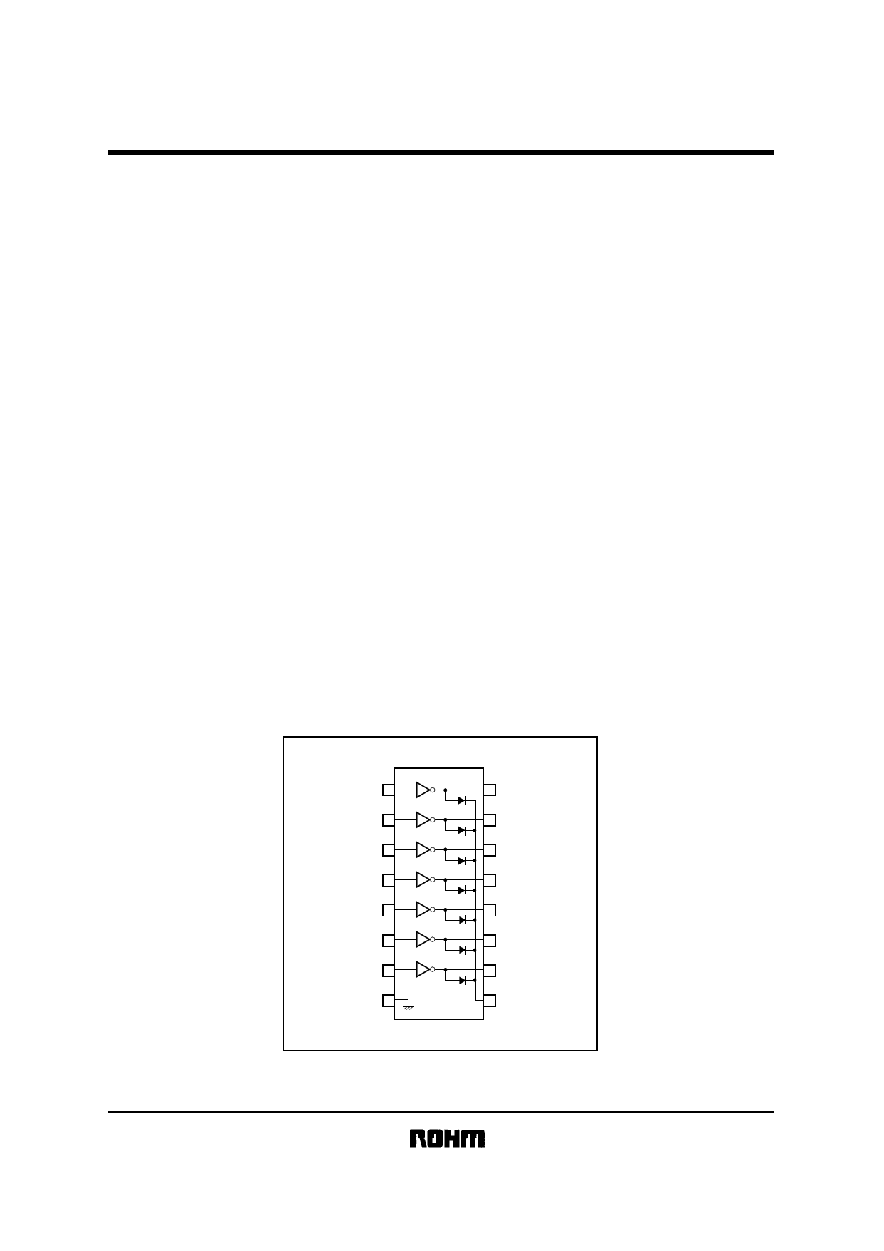
zBlock diagram
IN1 1
IN2 2
IN3 3
IN4 4
IN5 5
IN6 6
IN7 7
GND 8
16 OUT1
15 OUT2
14 OUT3
13 OUT4
12 OUT5
11 OUT6
10 OUT7
9 COM
1 page 
Standard ICs
BA12001B / BA12003B / BA12003BF / BA12004B
zElectrical characteristic curves
1400
Other than BA12003BF
1250
1200
1000
800 BA12003BF
625
600
400
200
0 25 50 75 100 125 150
AMBIENT TEMPERATURE : Ta (˚C)
Fig.7 Power dissipation vs. ambient
temperature
500
All series
400
300 2ch
3ch
200 4ch
5ch
100 6ch 7ch
0
10 20 30 40 50 60 70 80 90 100
DUTY CYCLE : (%)
Fig.8 Output conditions (I)
500
400
10% 20%
350
300
When all circuits are on
All series
Ta = 25˚C
200
Ta = 75˚C
100
110mA
64mA
0 20 40 60 80 100
DUTY CYCLE (%)
Fig.9 Output conditions (II)
500
The shaded range should
never be exceeded under
any circumstances
400
350
300
200 Max. usage conditions
Usage conditions range
100
0
10 20 30 40 50
SUPPLY VOLTAGE: VCC (V)
Fig.10 Usage conditions range
per circuit
5000
Ta = 25˚C
VCE = 2.0V
2000
1000
500
200
100
10
20 50 100 200 500 1000
OUTPUT CURRET : IOUT (mA)
Fig.11 DC current transfer ratio
vs. output current
500
IIN = 250µA
400
300
Ta = −30˚C
200
Ta = 25˚C
100
Ta = 80˚C
0
0 0.5 1.0 1.5 2.0 2.5
COLLECTOR TO EMITTER VOLTAGE : VCE (V)
Fig.12 Output current vs. voltage
between collector and emitter
500
IIN = 350µA
400
300
Ta = −30˚C
200
Ta = 25˚C
100
Ta = 80˚C
0
10 0.5 1.0 1.5 2.0 2.5
COLLECTOR TO EMITTER VOLTAGE : VCE (V)
Fig.13 Output current vs. voltage
between collector and emitter
500
IIN = 500µA
400
300
Ta = −30˚C
200
Ta = 25˚C
100
Ta = 80˚C
0
0 0.5 1.0 1.5 2.0 2.5
COLLECTOR TO EMITTER VOLTAGE : VCE (V)
Fig.14 Output current vs. voltage
between collector and emitter
20
15
Ta = −25˚C
Ta = 25˚C
Ta = 75˚C
10
5
0
10 20 30 40
INPUT VOLTAGE : VIN (V)
Fig.15 Input current vs. input
voltage (BA12003B / BF)
5 Page | ||
| Páginas | Total 6 Páginas | |
| PDF Descargar | [ Datasheet BA12004B.PDF ] | |
Hoja de datos destacado
| Número de pieza | Descripción | Fabricantes |
| BA12004B | High voltage/ high current Darlington transistor array | ROHM Semiconductor |
| BA12004BF | 7 Circuits Darlinton Transistor Array | ROHM Semiconductor |
| Número de pieza | Descripción | Fabricantes |
| SLA6805M | High Voltage 3 phase Motor Driver IC. |
Sanken |
| SDC1742 | 12- and 14-Bit Hybrid Synchro / Resolver-to-Digital Converters. |
Analog Devices |
|
DataSheet.es es una pagina web que funciona como un repositorio de manuales o hoja de datos de muchos de los productos más populares, |
| DataSheet.es | 2020 | Privacy Policy | Contacto | Buscar |