|
|
|
PDF EC635 Data sheet ( Hoja de datos )
| Número de pieza | EC635 | |
| Descripción | Designing with thermally protected TMOV Varistors in TVSS Applications | |
| Fabricantes | Littelfuse | |
| Logotipo | ||
Hay una vista previa y un enlace de descarga de EC635 (archivo pdf) en la parte inferior de esta página. Total 4 Páginas | ||
|
No Preview Available !
APPLICATION
NOTES
Designing with thermally protected TMOV
Varistors in TVSS Applications
Introduction
Metal Oxide Varistors (MOVs) are
commonly used to suppress transients in
many applications such as: Transient Voltage
Surge Suppressors (TVSS), Uninterruptible
Power Supplies (UPS), AC Power Taps, AC
Power Meters or other products. Lightning,
inductive load switching, or capacitor bank
switching, are often the sources of these
over-voltage transients. Under normal oper-
ating conditions, the AC line voltage applied
to an MOV is not expected to exceed the
MOV’s Maximum ACRMS Voltage Rating or
Maximum Continuous Operating Voltage
(MCOV). Occasionally, over-voltage tran-
sients may occur that exceeds these limits.
These transients are clamped to a suitable
voltage level by the MOV provided the tran-
sient energy does not exceed the MOV’s
maximum rating.
MOVs can also be subjected to continuous
abnormal voltage conditions rather than
short duration transients. If an MOV is
subjected to a sustained abnormal over-volt-
age, limited current condition (as is required
in UL1449), the MOV may go into thermal
runaway resulting in overheating, smoke, and
potentially fire. For end products to comply
with UL1449, some level of protection must
be afforded to the MOV to prevent this fail-
ure mode. That protection has traditionally
been a thermal fuse or Thermal Cut-Off
(TCO) device.
UL1449 Abnormal
Overvoltage, Limited
Current Requirements
In AC line applications, the loss of a Neutral-
Ground connection may occur in such a way
that there exists a risk that a sustained over-
voltage may be applied to an MOV that is
rated for a much lower continuous voltage.
In an unlimited current condition the MOV
will first fail to a low impedance (few Ohms),
but due to the high amount of energy avail-
able, it most often ruptures instantaneously.
If, however, there are loads tied to the AC
line that limit current flow, the MOV can
overheat and potentially cause the TVSS
device to overheat resulting in smoke, out-
gassing and eventually fire.
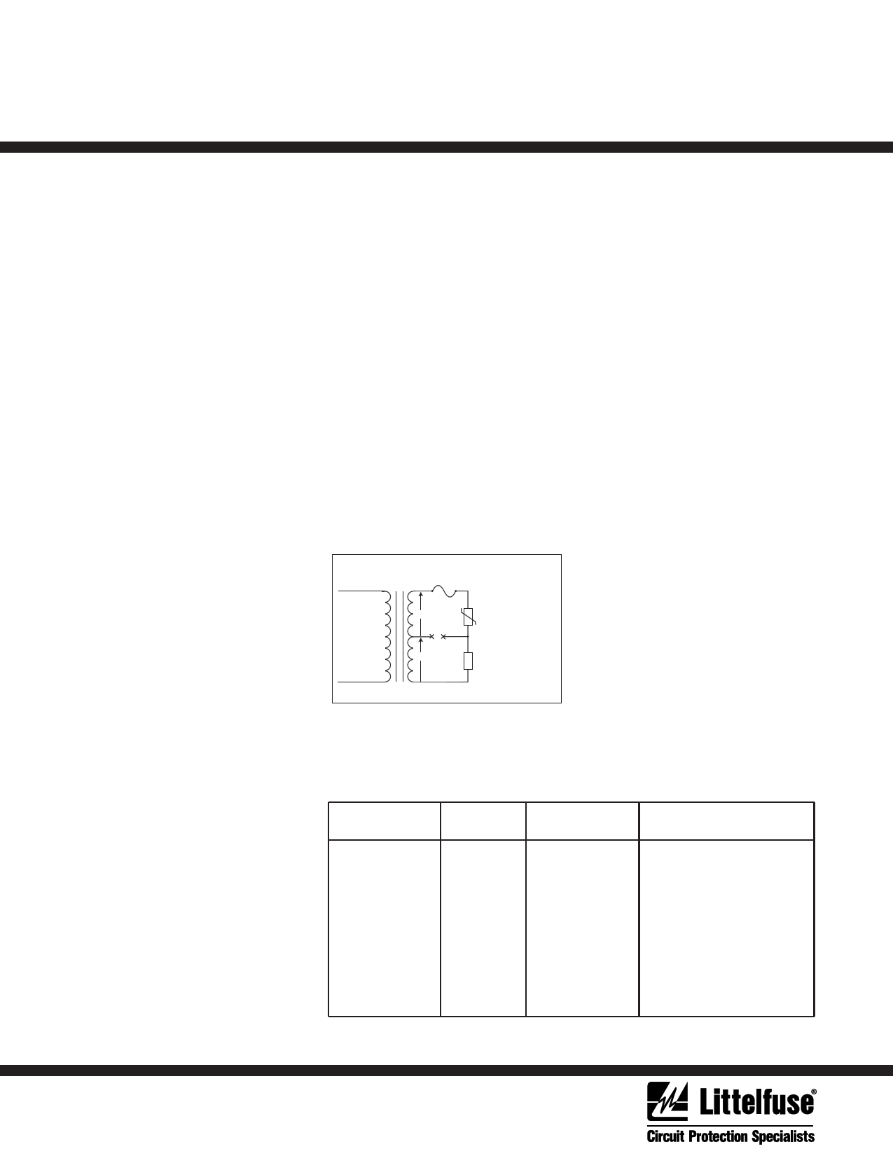
For example, in a standard U.S. 120V AC
Line application, two 120V AC power lines
(180° out of phase) are commonly fed from
a center-tapped 240V transformer. See
Figure 1. Let’s assume a 150V rated MOV is
present in the top 120V circuit, and some
load exists on the bottom 120V circuit. Both
the MOV and load share the center tap
which is the Neutral-Ground Connection. If
a break occurs on the center tap (X—X),
then the load in the bottom phase acts as a
current limiter and the line fuse may not
clear. In this scenario, the 150V rated MOV
is subjected to 240V at a limited current
potentially resulting in thermal run away for
the MOV.
Fuse
120V
120V
MOV rated for 150V rms
continuous voltage
Load
Figure 1. Possible Fault Condition for a limited current
abnormal overvoltage event
requires that end-product manufacturers
include a thermal protection element for an
MOV.
Table 1. defines the test voltage that should
be applied to various TVSS devices depend-
ing on the designer’s desired device1 rating.
Each test voltage is applied across each
conductor pair with a short circuit current of
5A, 2.5A, 0.5A and 0.125A respectively
across each of four TVSS devices. Since this
test is destructive, four devices are needed
to test for each of the four short circuit
currents. The four devices must be ener-
gized for 7 hours, or until current or
temperatures within the TVSS device attain
equilibrium, or until the TVSS becomes
disconnected from the AC Line.
For example shown in Figure 1, in a standard
120V AC Line application, the requirement is
for a 240VACRMS test voltage to be applied
across all conductor pairs. There are three
pairs; Line-Neutral (L-N), Line-Ground (L-
G), and Neutral-Ground (N-G). Again, this
test voltage is chosen because in the U.S.,
120V AC power is commonly fed from a
center-tapped 240V transformer. Thermally
unprotected MOVs for this application are
typically rated from 130Vacrms to
150Vacrms and will heat up, out-gas and may
catch fire in such circumstances.
This potential condition is specifically identi-
fied and addressed in the UL1449 TVSS
Standard. See Table 1. In many cases, it
Device Rating Phase Test Voltage(a)
110-120V
Single
110-120V/220-240V
Split
120/208V
3-wye
220-240
Single
220-240V/380-415V 3-wye
240V
High Leg Delta
254-277V
Single
254-277V/440-480V 3-wye
480V
High Leg Delta
347V
Single
347/600V
3-wye
240
240
208
415
415
240
480
480
480
600
600
Voltage Rating of
Conductor Pair
All
110-120V
120V
All
220-240V
120V
All
254-277V
254-277V
All
347V
Table 1. Test voltage Selection Table
(a.) For device ratings not specified in this table, the test voltage shall be the maximum phase voltage (if available) or twice
the conductor pair voltage ratings up to 600V max.
1 page | ||
| Páginas | Total 4 Páginas | |
| PDF Descargar | [ Datasheet EC635.PDF ] | |
Hoja de datos destacado
| Número de pieza | Descripción | Fabricantes |
| EC635 | Designing with thermally protected TMOV Varistors in TVSS Applications | Littelfuse |
| Número de pieza | Descripción | Fabricantes |
| SLA6805M | High Voltage 3 phase Motor Driver IC. |
Sanken |
| SDC1742 | 12- and 14-Bit Hybrid Synchro / Resolver-to-Digital Converters. |
Analog Devices |
|
DataSheet.es es una pagina web que funciona como un repositorio de manuales o hoja de datos de muchos de los productos más populares, |
| DataSheet.es | 2020 | Privacy Policy | Contacto | Buscar |