|
|
|
PDF DS2155 Data sheet ( Hoja de datos )
| Número de pieza | DS2155 | |
| Descripción | 3V EconOscillator/Divider | |
| Fabricantes | Dallas Semiconducotr | |
| Logotipo | ||
Hay una vista previa y un enlace de descarga de DS2155 (archivo pdf) en la parte inferior de esta página. Total 30 Páginas | ||
|
No Preview Available !
www.DataSheet4U.com
DS2155
T1/E1/J1 Single-Chip Transceiver
www.maxim-ic.com
GENERAL DESCRIPTION
The DS2155 is a software-selectable T1, E1, or J1
single-chip transceiver (SCT) for short-haul and
long-haul applications. The DS2155 is composed of a
line interface unit (LIU), framer, HDLC controllers,
and a TDM backplane interface, and is controlled by
an 8-bit parallel port configured for Intel or Motorola
bus operations. The DS2155 is pin and software
compatible with the DS2156.
The LIU is composed of transmit and receive
interfaces and a jitter attenuator. The transmit
interface is responsible for generating the necessary
waveshapes for driving the network and providing
the correct source impedance depending on the type
of media used. T1 waveform generation includes
DSX-1 line buildouts as well as CSU line buildouts
of -7.5dB, -15dB, and -22.5dB. E1 waveform
generation includes G.703 waveshapes for both 75Ω
coax and 120Ω twisted cables. The receive interface
provides network termination and recovers clock and
data from the network.
APPLICATIONS
T1/E1/J1 Line Cards
Switches and Routers
Add-Drop Multiplexers
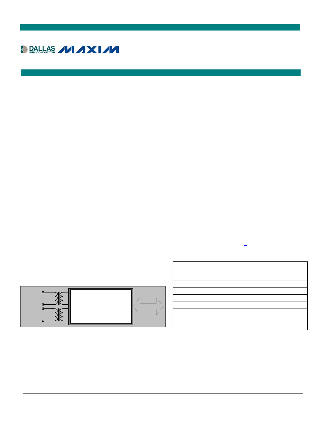
T1/E1/J1
NETWORK
DS2155
T1/E1/J1
SCT
BACKPLANE
TDM
FEATURES
Complete T1/DS1/ISDN-PRI/J1 Transceiver
Functionality
Complete E1 (CEPT) PCM-30/ISDN-PRI
Transceiver Functionality
Long-Haul and Short-Haul Line Interface for
Clock/Data Recovery and Waveshaping
CMI Coder/Decoder for Optical I/F
Crystal-Less Jitter Attenuator
Fully Independent Transmit and Receive
Functionality
Dual HDLC Controllers
Programmable BERT Generator and Detector
Internal Software-Selectable Receive and
Transmit-Side Termination Resistors for
75Ω/100Ω/120Ω T1 and E1 Interfaces
Dual Two-Frame Elastic-Store Slip Buffers that
Connect to Asynchronous Backplanes Up to
16.384MHz
16.384MHz, 8.192MHz, 4.096MHz, or
2.048MHz Clock Output Synthesized to
Recovered Network Clock
Features continued in Section 3.
ORDERING INFORMATION
PART
TEMP RANGE PIN-PACKAGE
DS2155L
DS2155L+
DS2155LN
DS2155LN+
DS2155G
DS2155G+
DS2155GN
DS2155GN
0°C to +70°C
0°C to +70°C
-40°C to +85°C
-40°C to +85°C
0°C to +70°C
0°C to +70°C
-40°C to +85°C
-40°C to +85°C
100 LQFP
100 LQFP
100 LQFP
100 LQFP
100 CSBGA
100 CSBGA
100 CSBGA
100 CSBGA
+ Denotes a lead-free/RoHS-compliant package.
Note: Some revisions of this device may incorporate deviations from published specifications known as errata. Multiple revisions of any device
may be simultaneously available through various sales channels. For information about device errata, click here: www.maxim-ic.com/errata.
1 of 238
REV: 080607
1 page 
DS2155
28.1 CHANNEL INTERLEAVE .........................................................................................................................184
28.2 FRAME INTERLEAVE..............................................................................................................................184
29. EXTENDED SYSTEM INFORMATION BUS (ESIB) .......................................................................187
30. PROGRAMMABLE BACKPLANE CLOCK SYNTHESIZER ........................................................191
31. FRACTIONAL T1/E1 SUPPORT .........................................................................................................191
32. USER-PROGRAMMABLE OUTPUT PINS........................................................................................193
33. TRANSMIT FLOW DIAGRAMS .........................................................................................................194
34. JTAG BOUNDARY SCAN ARCHITECTURE AND TEST ACCESS PORT .................................199
34.1 DESCRIPTION .........................................................................................................................................199
34.2 INSTRUCTION REGISTER........................................................................................................................202
34.3 TEST REGISTERS....................................................................................................................................204
34.4 BOUNDARY SCAN REGISTER .................................................................................................................204
34.5 BYPASS REGISTER .................................................................................................................................204
34.6 IDENTIFICATION REGISTER....................................................................................................................204
35. FUNCTIONAL TIMING DIAGRAMS.................................................................................................208
35.1 T1 MODE ...............................................................................................................................................208
35.2 E1 MODE ...............................................................................................................................................213
36. OPERATING PARAMETERS ..............................................................................................................222
37. AC TIMING PARAMETERS AND DIAGRAMS ...............................................................................224
37.1 MULTIPLEXED BUS AC CHARACTERISTICS ..........................................................................................224
37.2 NONMULTIPLEXED BUS AC CHARACTERISTICS ...................................................................................227
37.3 RECEIVE-SIDE AC CHARACTERISTICS ..................................................................................................230
37.4 BACKPLANE CLOCK TIMING: AC CHARACTERISTICS .........................................................................233
37.5 TRANSMIT AC CHARACTERISTICS ........................................................................................................234
38. PACKAGE INFORMATION ................................................................................................................237
38.1 100-PIN LQFP (56-G5002-000) ............................................................................................................237
38.2 100-BALL CSBGA (56-G6008-001) .....................................................................................................238
5 of 238
5 Page 
Flexible signaling support
– Software or hardware based
– Interrupt generated on change of signaling data
– Receive signaling freeze on loss-of-sync,
carrier loss, or frame slip
Addition of hardware pins to indicate carrier loss
and signaling freeze
Automatic RAI generation to ETS 300 011
specifications
Access to Sa and Si bits
Option to extend carrier loss criteria to a 1ms
period as per ETS 300 233
Japanese J1 support
– Ability to calculate and check CRC6 according
to the Japanese standard
– Ability to generate Yellow Alarm according to
the Japanese standard
TDM Bus
Dual two-frame independent receive and transmit
elastic stores
– Independent control and clocking
– Controlled slip capability with status
– Minimum delay mode supported
16.384MHz maximum backplane burst rate
Supports T1 to CEPT (E1) conversion
Programmable output clocks for fractional T1, E1,
H0, and H12 applications
Interleaving PCM bus operation
Hardware signaling capability
– Receive signaling reinsertion to a backplane
multiframe sync
– Availability of signaling in a separate PCM
data stream
– Signaling freezing
Ability to pass the T1 F-bit position through the
elastic stores in the 2.048MHz backplane mode
Access to the data streams in between the
framer/formatter and the elastic stores
User-selectable synthesized clock output
DS2155
Test and Diagnostics
Programmable on-chip bit error-rate testing
Pseudorandom patterns including QRSS
User-defined repetitive patterns
Daly pattern
Error insertion single and continuous
Total bit and errored bit counts
Payload error insertion
Error insertion in the payload portion of the T1
frame in the transmit path
Errors can be inserted over the entire frame or
selected channels
Insertion options include continuous and absolute
number with selectable insertion rates
F-bit corruption for line testing
Loopbacks: remote, local, analog, and per-channel
loopback
Extended System Information Bus
Host can read interrupt and alarm status on up to 8
ports with a single bus read
User-Programmable Output Pins
Four user-defined output pins for controlling
external logic
Control Port
8-bit parallel control port
Multiplexed or nonmultiplexed buses
Intel or Motorola formats
Supports polled or interrupt environments
Software access to device ID and silicon revision
Software reset supported
– Automatic clear on power-up
Hardware reset pin
HDLC Controllers
Two independent HDLC controllers
Fast load and unload features for FIFOs
SS7 support for FISU transmit and receive
Independent 128-byte Rx and Tx buffers with
interrupt support
Access FDL, Sa, or single/multiple DS0 channels
DS0 access includes Nx64 or Nx56
Compatible with polled or interrupt driven
environments
Bit-oriented code (BOC) support
11 of 238
11 Page | ||
| Páginas | Total 30 Páginas | |
| PDF Descargar | [ Datasheet DS2155.PDF ] | |
Hoja de datos destacado
| Número de pieza | Descripción | Fabricantes |
| DS2151 | T1 Single-Chip Transceiver | Dallas Semiconducotr |
| DS2151Q | T1 Single-Chip Transceiver | Dallas Semiconducotr |
| DS2152 | Enhanced T1 Single-Chip Transceiver | Dallas Semiconducotr |
| DS2152L | Enhanced T1 Single-Chip Transceiver | Dallas Semiconducotr |
| Número de pieza | Descripción | Fabricantes |
| SLA6805M | High Voltage 3 phase Motor Driver IC. |
Sanken |
| SDC1742 | 12- and 14-Bit Hybrid Synchro / Resolver-to-Digital Converters. |
Analog Devices |
|
DataSheet.es es una pagina web que funciona como un repositorio de manuales o hoja de datos de muchos de los productos más populares, |
| DataSheet.es | 2020 | Privacy Policy | Contacto | Buscar |