|
|
|
PDF DAC7744 Data sheet ( Hoja de datos )
| Número de pieza | DAC7744 | |
| Descripción | 16-Bit/ Quad Voltage Output DIGITAL-TO-ANALOG CONVERTER | |
| Fabricantes | Burr-Brown Corporation | |
| Logotipo | ||
Hay una vista previa y un enlace de descarga de DAC7744 (archivo pdf) en la parte inferior de esta página. Total 23 Páginas | ||
|
No Preview Available !
®
DAC7744
DAC7744
For most current data sheet and other product
information, visit www.burr-brown.com
16-Bit, Quad Voltage Output
DIGITAL-TO-ANALOG CONVERTER
FEATURES
q LOW POWER: 200mW
q UNIPOLAR OR BIPOLAR OPERATION
q SINGLE-SUPPLY OUTPUT RANGE: +10V
q DUAL SUPPLY OUTPUT RANGE: ±10V
q SETTLING TIME: 10µs to 0.003%
q 16-BIT MONOTONICITY: –40°C to +85°C
q PROGRAMMABLE RESET TO MID-SCALE
OR ZERO-SCALE
q DATA READBACK
q DOUBLE-BUFFERED DATA INPUTS
APPLICATIONS
q PROCESS CONTROL
q ATE PIN ELECTRONICS
q CLOSED-LOOP SERVO-CONTROL
q MOTOR CONTROL
q DATA ACQUISITION SYSTEMS
q DAC-PER-PIN PROGRAMMERS
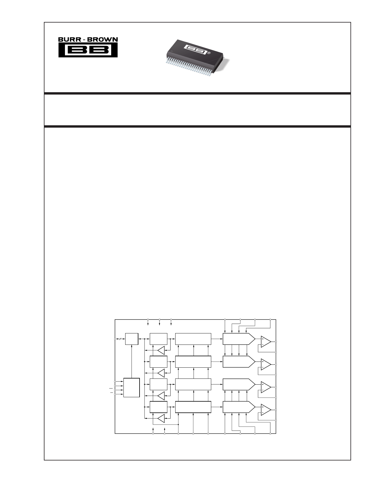
DAC7744
VDD VSS VCC
DESCRIPTION
The DAC7744 is a 16-bit, quad voltage output digital-
to-analog converter with guaranteed 16-bit monotonic
performance over the specified temperature range. It
accepts 16-bit parallel input data, has double-buffered
DAC input logic (allowing simultaneous update of all
DACs), and provides a readback mode of the internal
input registers. Programmable asynchronous reset
clears all registers to a mid-scale code of 8000H or to
a zero-scale of 0000H. The DAC7744 operates from
either a single +15V supply or from a +15V, –15V,
and +5V supply.
Low power and small size per DAC make the DAC7744
ideal for automatic test equipment, DAC-per-pin pro-
grammers, data acquisition systems, and closed-loop
servo-control. The DAC7744 is available in a 48-
lead SSOP package, and offers guaranteed specifica-
tions over the –40°C to +85°C temperature range.
VREFL
VREFH
AB Sense VREFL AB VREFH AB AB Sense
16 I/O
DATA I/O
Buffer
Input
Register A
Input
Register B
A1
A0 Control
CS Logic
R/W
Input
Register C
Input
Register D
DAC
Register A
DAC
Register B
DAC
Register C
DAC
Register D
DAC A
DAC B
DAC C
DAC D
VOUTA
VOUTA Sense
VOUTB
VOUTB Sense
VOUTC
VOUTC Sense
VOUTD
VOUTD Sense
AGND DGND
RST
RSTSEL LOADDACs VREFL VREFL CD VREFH CD VREFH
CD Sense
CD Sense
International Airport Industrial Park • Mailing Address: PO Box 11400, Tucson, AZ 85734 • Street Address: 6730 S. Tucson Blvd., Tucson, AZ 85706 • Tel: (520) 746-1111
Twx: 910-952-1111 • Internet: http://www.burr-brown.com/ • Cable: BBRCORP • Telex: 066-6491 • FAX: (520) 889-1510 • Immediate Product Info: (800) 548-6132
© 1999 Burr-Brown Corporation
PDS-11534A
PDrintAedCin U7.S7.A4. 4November, 1999
®
1 page 
PIN CONFIGURATION
Top View
DB15 (MSB) 1
DB14 2
DB13 3
DB12 4
DB11 5
DB10 6
DB9 7
DB8 8
DB7 9
DB6 10
DB5 11
DB4 12
DB3 13
DB2 14
DB1 15
DB0 (LSB) 16
RSTSEL 17
RST 18
LOADDACs 19
R/W 20
A1 21
A0 22
CS 23
DGND 24
DAC7744
SSOP
48 NC
47 NC
46 NC
45 NC
44 VOUTA Sense
43 VOUTA
42 VREFL AB Sense
41 VREFL AB
40 VREFH AB
39 VREFH AB Sense
38 VOUTB Sense
37 VOUTB
36 VOUTC Sense
35 VOUTC
34 VREFH CD Sense
33 VREFH CD
32 VREFL CD
31 VREFL CD Sense
30 VOUTD Sense
29 VOUTD
28 VSS
27 AGND
26 VCC
25 VDD
PIN DESCRIPTIONS
PIN
NAME
DESCRIPTION
1
DB15
Data Bit 15, MSB
2
DB14
Data Bit 14
3
DB13
Data Bit 13
4
DB12
Data Bit 12
5
DB11
Data Bit 11
6
DB10
Data Bit 10
7
DB9
Data Bit 9
8
DB8
Data Bit 8
9
DB7
Data Bit 7
10
DB6
Data Bit 6
11
DB5
Data Bit 5
12
DB4
Data Bit 4
13
DB3
Data Bit 3
14
DB2
Data Bit 2
15
DB1
Data Bit 1
16
DB0
Data Bit 0, LSB
17
RSTSEL
Reset Select. Determines the action of RST. If
HIGH, a RST command will set the DAC regis-
ters to mid-scale. If LOW, a RST command will
set the DAC registers to zero.
18
RST
Reset, Edge-Triggered. Depending on the state
of RSTSEL, the DAC Input and Output registers
are set to either mid-scale or zero.
19 LOADDACs DAC Output Registers Load Control. Rising edge
triggered.
20
R/W
Enabled by the CS, controls data read and write
from the input register.
21 A1 Enabled by the CS, in combination with A0
selects the Individual DAC Input Registers.
22 A0 Enabled by the CS, in combination with A1
selects the individual DAC input registers.
23 CS Chip Select, Active LOW.
24
DGND
Digital Ground
25 VDD Positive Power Supply
26 VCC Positive Power Supply
27
AGND
Analog Ground
28 VSS Negative Power Supply
29
VOUTD
DAC D Voltage Output
30 VOUTD Sense DAC D’s Output Amplifier Inverting Input. Used
to close the feedback loop at the load.
31 VREFL CD Sense DAC C and D Reference Low Sense Input
32
VREFL CD
DAC C and D Reference Low Input
33
VREFH CD
DAC C and D Reference High Input
34 VREFH CD Sense DAC C and D Reference High Sense Input
35
VOUTC
DAC C Voltage Output
36 VOUTC Sense DAC C’s Output Amplifier Inverting Input. Used
to close the feedback loop at the load.
37
VOUTB
DAC B Voltage Output
38 VOUTB Sense DAC B’s Output Amplifier Inverting Input. Used
to close the feedback loop at the load.
39 VREFH AB Sense DAC A and B Reference High Sense Input
40
VREFH AB
DAC A and B Reference High Input
41
VREFL AB
DAC A and B Reference Low Input
42 VREFL AB Sense DAC A and B Reference Low Sense Input
43
VOUTA
DAC A Voltage Input
44 VOUTA Sense DAC A’s Output Amplifier Inverting Input. Used
to close the feedback loop at the load.
45 NC No Connection
46 NC No Connection
47 NC No Connection
48 NC No Connection
®
5 DAC7744
5 Page 
TYPICAL PERFORMANCE CURVES: VSS = –15V
At TA = +25°C, VDD = +5V, VCC = +15V, VSS = –15V, VREFH = +10V, and VREFL = –10V, representative unit, unless otherwise specified.
+25°C
2.0
1.5
1.0
0.5
0
–0.5
–1.0
–1.5
–2.0
LINEARITY ERROR AND
DIFFERENTIAL LINEARITY ERROR vs CODE
(DAC A, +25°C)
2.0
1.5
1.0
0.5
0
–0.5
–1.0
–1.5
–2.0
0000H 2000H
4000H
6000H
8000H
A000H C000H
E000H FFFFH
Digital Input Code
LINEARITY ERROR AND
DIFFERENTIAL LINEARITY ERROR vs CODE
(DAC B, +25°C)
2.0
1.5
1.0
0.5
0
–0.5
–1.0
–1.5
–2.0
2.0
1.5
1.0
0.5
0
–0.5
–1.0
–1.5
–2.0
0000H 2000H
4000H 6000H
8000H
A000H C000H
E000H FFFFH
Digital Input Code
LINEARITY ERROR AND
DIFFERENTIAL LINEARITY ERROR vs CODE
(DAC C, +25°C)
2.0
1.5
1.0
0.5
0
–0.5
–1.0
–1.5
–2.0
2.0
1.5
1.0
0.5
0
–0.5
–1.0
–1.5
–2.0
0000H 2000H
4000H
6000H
8000H
A000H C000H
E000H FFFFH
Digital Input Code
+85°C
LINEARITY ERROR AND
DIFFERENTIAL LINEARITY ERROR vs CODE
(DAC A, +85°C)
2.0
1.5
1.0
0.5
0
–0.5
–1.0
–1.5
–2.0
2.0
1.5
1.0
0.5
0
–0.5
–1.0
–1.5
–2.0
0000H 2000H
4000H
6000H
8000H
A000H C000H
E000H FFFFH
Digital Input Code
LINEARITY ERROR AND
DIFFERENTIAL LINEARITY ERROR vs CODE
(DAC D, +25°C)
2.0
1.5
1.0
0.5
0
–0.5
–1.0
–1.5
–2.0
2.0
1.5
1.0
0.5
0
–0.5
–1.0
–1.5
–2.0
0000H 2000H
4000H 6000H
8000H
A000H C000H
E000H FFFFH
Digital Input Code
LINEARITY ERROR AND
DIFFERENTIAL LINEARITY ERROR vs CODE
(DAC B, +85°C)
2.0
1.5
1.0
0.5
0
–0.5
–1.0
–1.5
–2.0
2.0
1.5
1.0
0.5
0
–0.5
–1.0
–1.5
–2.0
0000H 2000H
4000H
6000H
8000H
A000H C000H
E000H FFFFH
Digital Input Code
®
11 DAC7744
11 Page | ||
| Páginas | Total 23 Páginas | |
| PDF Descargar | [ Datasheet DAC7744.PDF ] | |
Hoja de datos destacado
| Número de pieza | Descripción | Fabricantes |
| DAC7741 | 16-Bit/ Single Channel DIGITAL-TO-ANALOG CONVERTER With Internal Reference and Parallel Interface | Burr-Brown Corporation |
| DAC7741 | 16-Bit Voltage Output Digital-To-Analog Converter (Rev. B) | Texas Instruments |
| DAC7741Y | 16-Bit/ Single Channel DIGITAL-TO-ANALOG CONVERTER With Internal Reference and Parallel Interface | Burr-Brown Corporation |
| DAC7741YB | 16-Bit/ Single Channel DIGITAL-TO-ANALOG CONVERTER With Internal Reference and Parallel Interface | Burr-Brown Corporation |
| Número de pieza | Descripción | Fabricantes |
| SLA6805M | High Voltage 3 phase Motor Driver IC. |
Sanken |
| SDC1742 | 12- and 14-Bit Hybrid Synchro / Resolver-to-Digital Converters. |
Analog Devices |
|
DataSheet.es es una pagina web que funciona como un repositorio de manuales o hoja de datos de muchos de los productos más populares, |
| DataSheet.es | 2020 | Privacy Policy | Contacto | Buscar |