|
|
|
PDF AD7846 Data sheet ( Hoja de datos )
| Número de pieza | AD7846 | |
| Descripción | LC2MOS 16-Bit Voltage Output DAC | |
| Fabricantes | Analog Devices | |
| Logotipo | ||
Hay una vista previa y un enlace de descarga de AD7846 (archivo pdf) en la parte inferior de esta página. Total 16 Páginas | ||
|
No Preview Available !
a
LC2MOS
16-Bit Voltage Output DAC
FEATURES
16-Bit Monotonicity over Temperature
؎2 LSBs Integral Linearity Error
Microprocessor Compatible with Readback Capability
Unipolar or Bipolar Output
Multiplying Capability
Low Power (100 mW Typical)
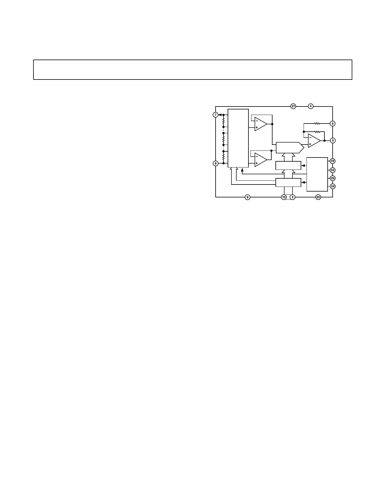
AD7846
FUNCTIONAL BLOCK DIAGRAM
VCC
VDD
VREF +
R
16
R
SEGMENT
SWITCH
MATRIX
VREF –
R
4
A2
A1
AD7846
R
R
12-BIT DAC
12
DAC LATCH
12
I/O LATCH
A3
CONTROL
LOGIC
RIN
VOUT
CS
R/ W
LDAC
CLR
GENERAL DESCRIPTION
The AD7846 is a 16-bit DAC constructed with Analog Devices’
LC2MOS process. It has VREF+ and VREF– reference inputs and
an on-chip output amplifier. These can be configured to give a
unipolar output range (0 V to +5 V, 0 V to +10 V) or bipolar
output ranges (± 5 V, ± 10 V).
The DAC uses a segmented architecture. The 4 MSBs in the
DAC latch select one of the segments in a 16-resistor string.
Both taps of the segment are buffered by amplifiers and fed to a
12-bit DAC, which provides a further 12 bits of resolution. This
architecture ensures 16-bit monotonicity. Excellent integral
linearity results from tight matching between the input offset
voltages of the two buffer amplifiers.
In addition to the excellent accuracy specifications, the AD7846
also offers a comprehensive microprocessor interface. There are
16 data I/O pins, plus control lines (CS, R/W, LDAC and CLR).
R/W and CS allow writing to and reading from the I/O latch.
This is the readback function which is useful in ATE applica-
tions. LDAC allows simultaneous updating of DACs in a multi-
DAC system and the CLR line will reset the contents of the
DAC latch to 00 . . . 000 or 10 . . . 000 depending on the state
of R/W. This means that the DAC output can be reset to 0 V in
both the unipolar and bipolar configurations.
The AD7846 is available in 28-lead plastic, ceramic, and PLCC
packages.
VSS
DB15 DB0
DGND
PRODUCT HIGHLIGHTS
1. 16-Bit Monotonicity
The guaranteed 16-bit monotonicity over temperature makes
the AD7846 ideal for closed-loop applications.
2. Readback
The ability to read back the DAC register contents minimizes
software routines when the AD7846 is used in ATE systems.
3. Power Dissipation
Power dissipation of 100 mW makes the AD7846 the lowest
power, high accuracy DAC on the market.
REV. E
Information furnished by Analog Devices is believed to be accurate and
reliable. However, no responsibility is assumed by Analog Devices for its
use, nor for any infringements of patents or other rights of third parties
which may result from its use. No license is granted by implication or
otherwise under any patent or patent rights of Analog Devices.
One Technology Way, P.O. Box 9106, Norwood, MA 02062-9106, U.S.A.
Tel: 781/329-4700 World Wide Web Site: http://www.analog.com
Fax: 781/326-8703
© Analog Devices, Inc., 2000
1 page 
PIN CONFIGURATIONS
DIP
DB2 1
28 DB3
DB1 2
27 DB4
DB0 3
26 DB5
VDD 4
25 LDAC
VOUT 5
24 CLR
RIN
VREF+
VREF–
6 AD7846 23 CS
7 TOP VIEW 22 R/W
8 (Not to Scale) 21 VCC
VSS 9
20 DGND
DB15 10
19 DB6
DB14 11
18 DB7
DB13 12
17 DB8
DB12 13
16 DB9
DB11 14
15 DB10
PLCC
4 3 2 1 28 27 26
VOUT 5
RIN 6
VREF+ 7
VREF– 8
VSS 9
DB15 10
DB14 11
PIN 1
IDENTIFIER
AD7846
TOP VIEW
(Not to Scale)
25 LDAC
24 CLR
23 CS
22 R/W
21 VCC
20 DGND
19 DB6
12 13 14 15 16 17 18
AD7846
PIN FUNCTION DESCRIPTION
Pin Mnemonic
1–3 DB2–DB0
4 VDD
5 VOUT
6 RIN
7 VREF+
8 VREF–
9 VSS
10–19 DB15–DB6
20 DGND
21 VCC
22 R/W
23 CS
24 CLR
25 LDAC
26–28 DB5–DB3
Description
Data I/O pins. DB0 is LSB.
Positive supply for analog circuitry. This is
+15 V nominal.
DAC output voltage pin.
Input to summing resistor of DAC output
amplifier. This is used to select output
voltage ranges. See Table I.
VREF+ Input. The DAC is specified for VREF+
= +5 V.
VREF– Input. For unipolar operation con-
nect VREF– to 0 V and for bipolar operation
connect it to –5 V. The device is specified
for both conditions.
Negative supply for the analog circuitry.
This is –15 V nominal.
Data I/O pins. DB15 is MSB.
Ground pin for digital circuitry.
Positive supply for digital circuitry. This is
+5 V nominal.
R/W input. This can be used to load data to
the DAC or to read back the DAC latch
contents.
Chip select input. This selects the device.
Clear input. The DAC can be cleared to
000 . . . 000 or 100 . . . 000. See Table II.
Asynchronous load input to DAC.
Data I/O pins.
Table I. Output Voltage Ranges
Output Range
0 V to +5 V
0 V to +10 V
+5 V to –5 V
+5 V to –5 V
+10 V to –10 V
VREF+
+5 V
+5 V
+5 V
+5 V
+5 V
VREF–
0V
0V
–5 V
0V
–5 V
RIN
VOUT
0V
VOUT
+5 V
0V
REV. E
–5–
5 Page 
AD7846
POSITION MEASUREMENT APPLICATION
Figure 22 shows the AD7846 in a position measurement appli-
cation using an LVDT (Linear Variable Displacement Trans-
ducer), an AD630 synchronous demodulator and a comparator
to make a 16-bit LVDT-to-Digital Converter. The LVDT is
excited with a fixed frequency and fixed amplitude sine wave
(usually 2.5 kHz, 2 V pk-pk). The outputs of the secondary coil
are in antiphase and their relative amplitudes depend on the
position of the core in the LVDT. The AD7846 output interpo-
lates between these two inputs in response to the DAC input
code. The AD630 is set up so that it rectifies the DAC output
signal. Thus, if the output of the DAC is in phase with the
VREF+ input, the inverting input to the comparator will be posi-
tive, and if it is in phase with VREF–, the output will be negative.
By turning on each bit of the DAC in succession starting with
the MSB, and deciding to leave it on or turn it off based on the
comparator output, a 16-bit measurement of the core position is
obtained.
In a multiple DAC system, the double buffering of the AD7846
allows the user to simultaneously update all DACs. In Figure
24, a 16-bit word is loaded to the input latches of each of the
DACs in sequence. Then, with one instruction to the appropri-
ate address, CS4 (i.e., LDAC) is brought low, updating all the
DACs simultaneously.
ALE
8086
DEN
RD
WR
AD0–AD15
16-BIT
LATCH
ADDRESS BUS
ADDRESS
DECODE
CS
AD7846*
LDAC
DATA BUS
R/ W
CLR
+5V
DB0–DB15
ASIN t
LVDT x ASIN t
–(1–x)ASIN t
*ADDITIONAL PINS
OMITTED FOR CLARITY
VREF+ VOUT
RIN
AD7846*
VREF–
DGND
DB15 DB0
SIGNAL
GROUND
PROCESSOR DATA BUS
R1
100k⍀
C1
1F
AD630*
TO
PROCESSOR PORT
Figure 22. AD7846 in Position Measurement Application
MICROPROCESSOR INTERFACING
AD7846-to-8086 Interface
Figure 23 shows the 8086 16-bit processor interfacing to the
AD7846. The double buffering feature of the DAC is not used
in this circuit since LDAC is permanently tied to 0 V. AD0–
AD15 (the 16-bit data bus) are connected to the DAC data bus
(DB0–DB15). The 16-bit word is written to the DAC in one
MOV instruction and the analog output responds immediately.
In this example, the DAC address is D000H.
ADDRESS BUS
ALE
8086
DEN
RD
WR
16-BIT
LATCH
ADDRESS
DECODE
CS
LDAC
+5V CLR
AD7846*
R/ W
CS
AD7846*
LDAC
R/ W
CLR
DB0–DB15
+5V
*LINEAR CIRCUITRY
OMITTED FOR CLARITY
CS
AD7846*
LDAC
R/ W
CLR
DB0–DB15
+5V
Figure 24. AD7846-to-8086 Interface: Multiple DAC System
AD7846-to-MC68000 Interface
Interfacing between the AD7846 and MC68000 is accom-
plished using the circuit of Figure 25. The following routine
writes data to the DAC latches and then outputs the data via the
DAC latch.
1000
MOVE.W #W, D0
The desired DAC data, W,
is loaded into Data Regis-
ter 0. W may be any value
between 0 and 65535
(decimal) or 0 and FFFF
(hexadecimal).
MOVE.W D0, $E000 The data, W, is transferred
between D0 and the DAC
register.
MOVE.W #228, D7
TRAP #14
Control is returned to the
System Monitor using
these two instructions.
AD0–AD15
DATA BUS
*LINEAR CIRCUITRY
OMITTED FOR CLARITY
DB0–DB15
Figure 23. AD7846-to-8086 Interface Circuit
REV. E
–11–
11 Page | ||
| Páginas | Total 16 Páginas | |
| PDF Descargar | [ Datasheet AD7846.PDF ] | |
Hoja de datos destacado
| Número de pieza | Descripción | Fabricantes |
| AD7840 | LC2MOS Complete 14-Bit DAC | Analog Devices |
| AD7841 | Octal 14-Bit/ Parallel Input/ Voltage-Output DAC | Analog Devices |
| AD7843 | Touch Screen Digitizer | Analog Devices |
| AD7845 | LC2MOS Complete 12-Bit Multiplying DAC | Analog Devices |
| Número de pieza | Descripción | Fabricantes |
| SLA6805M | High Voltage 3 phase Motor Driver IC. |
Sanken |
| SDC1742 | 12- and 14-Bit Hybrid Synchro / Resolver-to-Digital Converters. |
Analog Devices |
|
DataSheet.es es una pagina web que funciona como un repositorio de manuales o hoja de datos de muchos de los productos más populares, |
| DataSheet.es | 2020 | Privacy Policy | Contacto | Buscar |