|
|
|
PDF AT89LV55-12PI Data sheet ( Hoja de datos )
| Número de pieza | AT89LV55-12PI | |
| Descripción | 8-Bit Microcontroller with 20K Bytes Flash | |
| Fabricantes | ATMEL Corporation | |
| Logotipo | ||
Hay una vista previa y un enlace de descarga de AT89LV55-12PI (archivo pdf) en la parte inferior de esta página. Total 23 Páginas | ||
|
No Preview Available !
203Features
• Compatible with MCS-51™ Products
• 20K Bytes of Reprogrammable Flash Memory
– Endurance: 1,000 Write/Erase Cycles
• Fully Static Operation: 0 Hz to 12 MHz
• Three-Level Program Memory Lock
• 256 x 8-bit Internal RAM
• 32 Programmable I/O Lines
• Three 16-bit Timer/Counters
• Eight Interrupt Sources
• Low Power Idle and Power Down Modes
• 2.7V to 6.0V Operating Range
Description
The AT89LV55 is a low-voltage, low-power CMOS 8-bit microcomputer with 20K
bytes of Flash programmable and erasable read only memory. The device is manu-
factured using Atmel’s high density nonvolatile memory technology and is compatible
with the industry standard 80C51 instruction set and pinout. The on-chip Flash allows
the program memory to be reprogrammed. By combining a versatile 8-bit CPU with
Flash on a monolithic chip, the Atmel AT89LV55 is a powerful microcomputer which
provides a highly flexible and cost effective solution to many embedded control appli-
cations.
(continued)
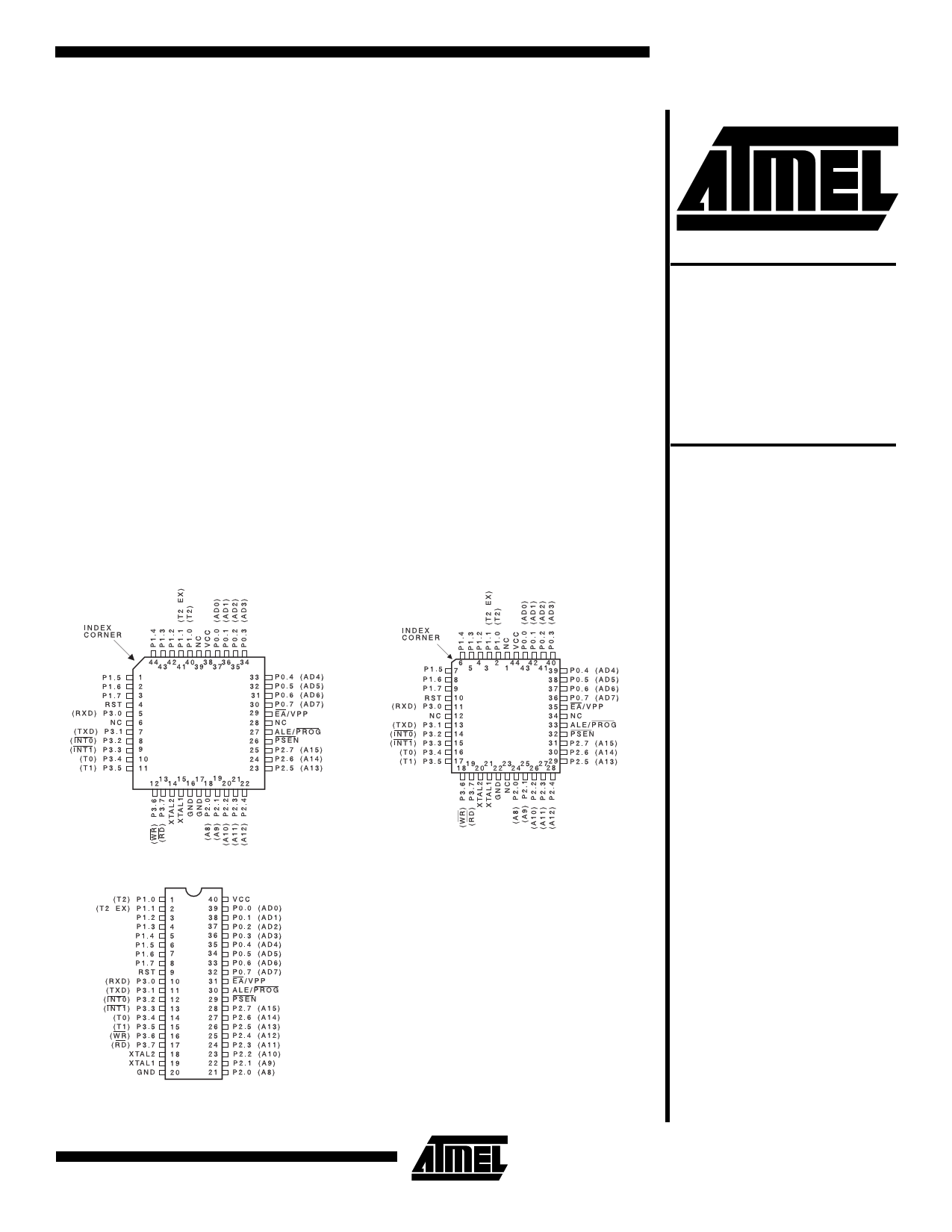
Pin Configurations
TQFP
PLCC
8-Bit
Microcontroller
with 20K Bytes
Flash
AT89LV55
PDIP
0811B-B–12/97
4-193
1 page 
AT89LV55
Table 1. AT89LV55 SFR Map and Reset Values
0F8H
0F0H
0E8H
0E0H
0D8H
0D0H
0C8H
0C0H
0B8H
0B0H
0A8H
0A0H
98H
90H
88H
80H
B
00000000
ACC
00000000
PSW
00000000
T2CON
00000000
IP
XX000000
P3
11111111
IE
0X000000
P2
11111111
SCON
00000000
P1
11111111
TCON
00000000
P0
11111111
T2MOD
XXXXXX00
SBUF
XXXXXXXX
TMOD
00000000
SP
00000111
RCAP2L
00000000
TL0
00000000
DPL
00000000
RCAP2H
00000000
TL1
00000000
DPH
00000000
TL2
00000000
TH0
00000000
TH2
00000000
TH1
00000000
0FFH
0F7H
0EFH
0E7H
0DFH
0D7H
0CFH
0C7H
0BFH
0B7H
0AFH
0A7H
9FH
97H
8FH
PCON
0XXX0000
87H
4-197
5 Page 
AT89LV55
Programmable Clock Out
A 50% duty cycle clock can be programmed to come out on
P1.0, as shown in Figure 5. This pin, besides being a regu-
lar I/O pin, has two alternate functions. It can be pro-
grammed to input the external clock for Timer/Counter 2 or
to output a 50% duty cycle clock ranging from 61 Hz to 3
MHz at a 12 MHz operating frequency.
To configure the Timer/Counter 2 as a clock generator, bit
C/T2 (T2CON.1) must be cleared and bit T2OE (T2MOD.1)
must be set. Bit TR2 (T2CON.2) starts and stops the timer.
The clock-out frequency depends on the oscillator fre-
quency and the reload value of Timer 2 capture registers
(RCAP2H, TCAP2L), as shown in the following equation:
Clock-Out Frequency = -4----×-----[---6---5--O-5----3s---6c---i-l-–-l-a--(-t-R-o---r-C---F-A---r-P-e---2q---Hu----e-,-R-n---c-C--y--A----P----2---L----)--]
In the clock-out mode, Timer 2 roll-overs will not generate
an interrupt. This behavior is similar to when Timer 2 is
used as a baud-rate generator. It is possible to use Timer 2
as a baud-rate generator and a clock generator simulta-
neously. Note, however, that the baud-rate and clock-out
frequencies cannot be determined independently from one
another since they both use RCAP2H and RCAP2L.
UART
The UART in the AT89LV55 operates the same way as the
UART in the AT89C51 and AT89C52. For further informa-
tion, see the Microcontroller Data Book, section titled,
“Serial Interface.”
Interrupts
The AT89LV55 has a total of six interrupt vectors: two
external interrupts (INT0 and INT1), three timer interrupts
(Timers 0, 1, and 2), and the serial port interrupt. These
interrupts are all shown in Figure 6.
Each of these interrupt sources can be individually enabled
or disabled by setting or clearing a bit in Special Function
Register IE. IE also contains a global disable bit, EA, which
disables all interrupts at once.
Note that Table 5 shows that bit position IE.6 is unimple-
mented. In the AT89C51 and AT89LV51, bit position IE.5 is
also unimplemented. User software should not write 1s to
these bit positions, since they may be used in future AT89
products.
Timer 2 interrupt is generated by the logical OR of bits TF2
and EXF2 in register T2CON. Neither of these flags is
cleared by hardware when the service routine is vectored
to. In fact, the service routine may have to determine
whether it was TF2 or EXF2 that generated the interrupt,
and that bit will have to be cleared in software.
The Timer 0 and Timer 1 flags, TF0 and TF1, are set at
S5P2 of the cycle in which the timers overflow. The values
are then polled by the circuitry in the next cycle. However,
the Timer 2 flag, TF2, is set at S2P2 and is polled in the
same cycle in which the timer overflows. For further infor-
mation, see the Microcontroller Data Book, section titled
“Interrupts.”
Table 5. Interrupt Enable (IE) Register
(MSB)
(LSB)
EA — ET2 ES ET1 EX1 ET0 EX0
Enable Bit = 1 enables the interrupt.
Enable Bit = 0 disables the interrupt.
Symbol Position Function
EA IE.7 Disables all interrupts. If EA = 0, no
interrupt is acknowledged. If EA = 1,
each interrupt source is individually
enabled or disabled by setting or
clearing its enable bit.
— IE.6 Reserved.
ET2 IE.5 Timer 2 interrupt enable bit.
ES IE.4 Serial Port interrupt enable bit.
ET1 IE.3 Timer 1 interrupt enable bit.
EX1 IE.2 External interrupt 1 enable bit.
ET0 IE.1 Timer 0 interrupt enable bit.
EX0 IE.0 External interrupt 0 enable bit.
User software should never write 1s to unimplemented bits,
because they may be used in future AT89 products.
Figure 6. Interrupt Sources
4-203
11 Page | ||
| Páginas | Total 23 Páginas | |
| PDF Descargar | [ Datasheet AT89LV55-12PI.PDF ] | |
Hoja de datos destacado
| Número de pieza | Descripción | Fabricantes |
| AT89LV55-12PC | 8-Bit Microcontroller with 20K Bytes Flash | ATMEL Corporation |
| AT89LV55-12PI | 8-Bit Microcontroller with 20K Bytes Flash | ATMEL Corporation |
| Número de pieza | Descripción | Fabricantes |
| SLA6805M | High Voltage 3 phase Motor Driver IC. |
Sanken |
| SDC1742 | 12- and 14-Bit Hybrid Synchro / Resolver-to-Digital Converters. |
Analog Devices |
|
DataSheet.es es una pagina web que funciona como un repositorio de manuales o hoja de datos de muchos de los productos más populares, |
| DataSheet.es | 2020 | Privacy Policy | Contacto | Buscar |