|
|
|
PDF CAT5401 Data sheet ( Hoja de datos )
| Número de pieza | CAT5401 | |
| Descripción | Quad Digitally Programmable Potentiometers (DPP) with 64 Taps and SPI Interface | |
| Fabricantes | Catalyst Semiconductor | |
| Logotipo | ||
Hay una vista previa y un enlace de descarga de CAT5401 (archivo pdf) en la parte inferior de esta página. Total 18 Páginas | ||
|
No Preview Available !
CAT5401
Quad Digitally Programmable Potentiometers (DPP™)
with 64 Taps and SPI Interface
FEATURES
ALOGEN FR
LEA D F REETM
s Four linear-taper digitally programmable
potentiometers
s 64 resistor taps per potentiometer
s End to end resistance 2.5kΩ, 10kΩ, 50kΩ or 100kΩ
s Potentiometer control and memory access via
SPI interface: Mode (0, 0) and (1, 1)
s Low wiper resistance, typically 80Ω
s Nonvolatile memory storage for up to four wiper
settings for each potentiometer
s Automatic recall of saved wiper settings at
power up
s 2.5 to 6.0 volt operation
s Standby current less than 1µA
s 1,000,000 nonvolatile WRITE cycles
s 100 year nonvolatile memory data retention
s 24-lead SOIC, 24-lead TSSOP and BGA
s Industrial temperature range
DESCRIPTION
The CAT5401 is four Digitally Programmable
Potentiometers (DPPs™) integrated with control logic
and 16 bytes of NVRAM memory. Each DPP consists of
a series of 63 resistive elements connected between two
externally accessible end points. The tap points between
each resistive element are connected to the wiper outputs
with CMOS switches. A separate 6-bit control register
(WCR) independently controls the wiper tap switches for
each DPP. Associated with each wiper control register
are four 6-bit non-volatile memory data registers (DR)
used for storing up to four wiper settings. Writing to the
wiper control register or any of the non-volatile data
registers is via a SPI serial bus. On power-up, the
contents of the first data register (DR0) for each of the
four potentiometers is automatically loaded into its
respective wiper control register.
The CAT5401 can be used as a potentiometer or as a
two terminal, variable resistor. It is intended for circuit
level or system level adjustments in a wide variety of
applications.
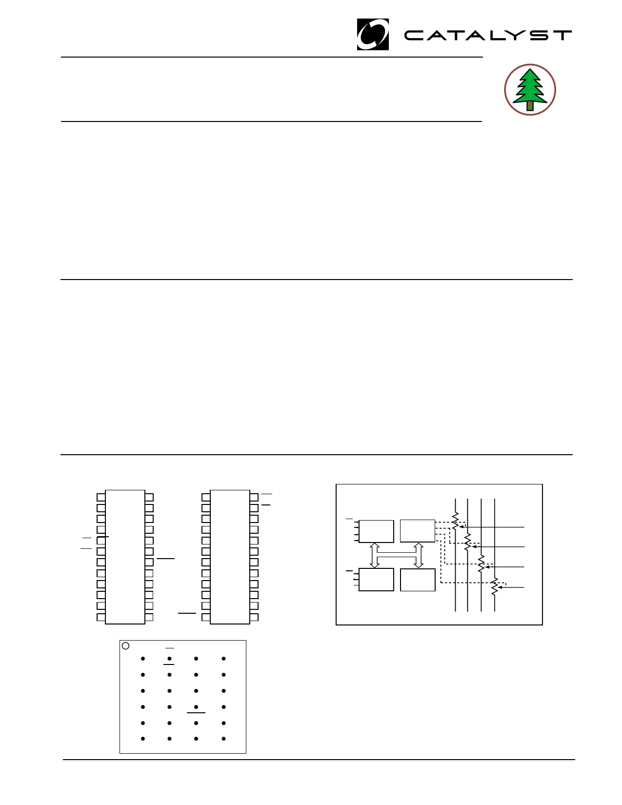
PIN CONFIGURATION
SOIC Package (J, W)
TSSOP Package (U, Y)
VCC
RL0
RH0
RW0
CS
WP
SI
A1
RL1
RH1
RW1
GND
1 24
2 23
3 22
4 21
5 20
6 CAT 19
7 5401 18
8 17
9 16
10 15
11 14
12 13
NC SI
RL3
RH3
RW3
A0
SO
A1
RL1
RH1
RW1
GND
HOLD NC
SCK
RL2
RW2
RH2
RH2 RL2
RW2 SCK
NC HOLD
1 24
2 23
3 22
4 21
5 20
6 CAT 19
7 5401 18
8 17
9 16
10 15
11 14
12 13
WP
CS
RW0
RH0
RL0
VCC
NC
RL3
RH3
RW3
A0
SO
FUNCTIONAL DIAGRAM
RH0 RH1 RH2 RH3
CS
SCK
SI
SO
SPI BUS
INTERFACE
WIPER
CONTROL
REGISTERS
WP CONTROL NONVOLATILE
A0 LOGIC
DATA
A1 REGISTERS
RL0 RL1 RL2 RL3
A
B
BGA C
D
E
F
1
RW0
RL0
VCC
NC
RL3
RW3
234
CS A1 RL1
WP
RH0
SI
RH1
RW1
VSS
RH3
SO
A0
RH2
HOLD
SCK
NC
RW2
RL2
Top View - Bump Side Down
R W0
R W1
R W2
R W3
© 2004 by Catalyst Semiconductor, Inc.
Characteristics subject to change without notice
1
Document No. 2010, Rev. F
1 page 
CAT5401
D.C. OPERATING CHARACTERISTICS
Over recommended operating conditions unless otherwise stated.
Symbol
ICC
ISB
ILI
ILO
VIL
VIH
VOL1
Parameter
Test Conditions
Power Supply Current
fSCK = 2MHz, SO Open
Inputs = GND
Standby Current (VCC = 5.0V) VIN = GND or VCC; SO Open
Input Leakage Current
VIN = GND to VCC
Output Leakage Current
VOUT = GND to VCC
Input Low Voltage
Input High Voltage
Output Low Voltage (VCC = 3.0V)
IOL = 3 mA
Min Typ
-1
VCC x 0.7
Max
1
1
10
10
VCC x 0.3
VCC + 1.0
0.4
Units
mA
µA
µA
µA
V
V
V
PIN CAPACITANCE (1)
Applicable over recommended operating range from TA=25˚C, f=1.0 MHz, VCC=+5.0V (unless otherwise noted).
Symbol Test Conditions
Min Typ Max Units
COUT Output Capacitance (SO)
8 pF
CIN Input Capacitance (CS, SCK, SI, WP, HOLD)
6 pF
Conditions
VOUT=0V
VIN=0V
5 Document No. 2010, Rev. F
5 Page 
Figure 10. Increment/Decrement Timing Limits
INC/DEC
Command
Issued
SCK
SI
RW Voltage Out
CAT5401
tWRID
INSTRUCTION FORMAT
Read Wiper Control Register (WCR)
DEVICE ADDRESSES INSTRUCTION
DATA
CS 0 1 0 1 0 0 A1 A0 1 0 0 1 0 0 P1 P0 7 6 5 4 3 2 1 0 CS
00
Write Wiper Control Register (WCR)
DEVICE ADDRESSES INSTRUCTION
DATA
CS 0 1 0 1 0 0 A1 A0 1 0 1 0 0 0 P1P0 7 6 5 4 3 2 1 0
00
CS
Read Data Register (DR)
DEVICE ADDRESSES INSTRUCTION
DATA
CS 0 1 0 1 0 0 A1 A0 1 0 1 1 R1 R0 P1P0 7 6 5 4 3 2 1 0 CS
Write Data Register (DR)
DEVICE ADDRESSES INSTRUCTION
DATA
CS 0 1 0 1 0 0 A1 A0 1 1 0 0 R1 R0 P1P0 7 6 5 4 3 2 1 0 CS High Voltage
Write Cycle
Read (WIP) Status
DEVICE ADDRESSES INSTRUCTION
DATA
CS 0 1 0 1 0 0 A1 A0 0 1 0 1 0 0 0 1 7 6 5 4 3 2 1 W CS
0000 0 0 0 I
P
11
Document No. 2010, Rev. F
11 Page | ||
| Páginas | Total 18 Páginas | |
| PDF Descargar | [ Datasheet CAT5401.PDF ] | |
Hoja de datos destacado
| Número de pieza | Descripción | Fabricantes |
| CAT5401 | Quad Digitally Programmable Potentiometers (DPP) with 64 Taps and SPI Interface | Catalyst Semiconductor |
| CAT5401 | Quad Digital Potentiometer | ON Semiconductor |
| CAT5409 | Quad Digital Potentiometer | ON Semiconductor |
| CAT5409 | Quad Digitally Programmable Potentiometers (DPP) | Catalyst Semiconductor |
| Número de pieza | Descripción | Fabricantes |
| SLA6805M | High Voltage 3 phase Motor Driver IC. |
Sanken |
| SDC1742 | 12- and 14-Bit Hybrid Synchro / Resolver-to-Digital Converters. |
Analog Devices |
|
DataSheet.es es una pagina web que funciona como un repositorio de manuales o hoja de datos de muchos de los productos más populares, |
| DataSheet.es | 2020 | Privacy Policy | Contacto | Buscar |