|
|
|
PDF EL5120T Data sheet ( Hoja de datos )
| Número de pieza | EL5120T | |
| Descripción | 12MHz Rail-to-Rail Input-Output Operational Amplifier | |
| Fabricantes | Intersil | |
| Logotipo | ||
Hay una vista previa y un enlace de descarga de EL5120T (archivo pdf) en la parte inferior de esta página. Total 14 Páginas | ||
|
No Preview Available !
NOc1NoT-8nOR8ta8ERc-CIEtNOCoTOuMErMMRTSMEeINcELhDNonEDricDEwaDFwl OSRwuRE.ipnPNptLeEoArrWstCiClED.ceMEonESmteNIG/rtTsNactS
12MHz Rail-to-Rail Input-Output Operational Amplifier
EL5120T
The EL5120T is a high voltage rail-to-rail input-output amplifier
with low power consumption. The EL5120T is a single amplifier
that exhibits beyond the rail input capability, rail-to-rail output
capability, and is unity gain stable.
The operating voltage range is from 4.5V to 19V. It can be
configured for single or dual supply operation, and typically
consumes only 750µA. The EL5120T has an output short circuit
capability of ±200mA and a continuous output current capability
of ±70mA.
The EL5120T features a slew rate of 12V/µs. Also, the device
provides common mode input capability beyond the supply rails,
rail-to-rail output capability, and a bandwidth of 12MHz (-3dB).
This enables the amplifier to offer maximum dynamic range at
any supply voltage. These features make the EL5120T an ideal
amplifier solution for use in TFT-LCD panels as a VCOM or static
gamma buffer, and in high speed filtering and signal conditioning
applications. Other applications include battery power and
portable devices, especially where low power consumption is
important.
The EL5120T is available in small 5 Ld TSOT package. It features a
standard operational amplifier pinout. The device operates over
an ambient temperature range of -40°C to +125°C.
Features
• 750µA supply current
• 12MHz (-3dB) bandwidth
• 4.5V to 19V maximum supply voltage range
• 12V/µs slew rate
• ±70mA continuous output current
• ±200mA output short circuit current
• Unity-gain stable
• Beyond the rails input capability
• Rail-to-rail output swing
• Built-in thermal protection
• -40°C to +125°C ambient temperature range
• Pb-free (RoHS compliant)
Applications
• TFT-LCD panel - tablet, monitor, notebook
- VCOM amplifier, static gamma buffer, panel repair
• Electronic notebooks, games
• Touch-screen displays
• Personal communication devices, digital assistants (PDA)
• Portable instrumentation
• Sampling ADC amplifiers
• Wireless LANs
• Office automation
• Active filters
• ADC/DAC buffer
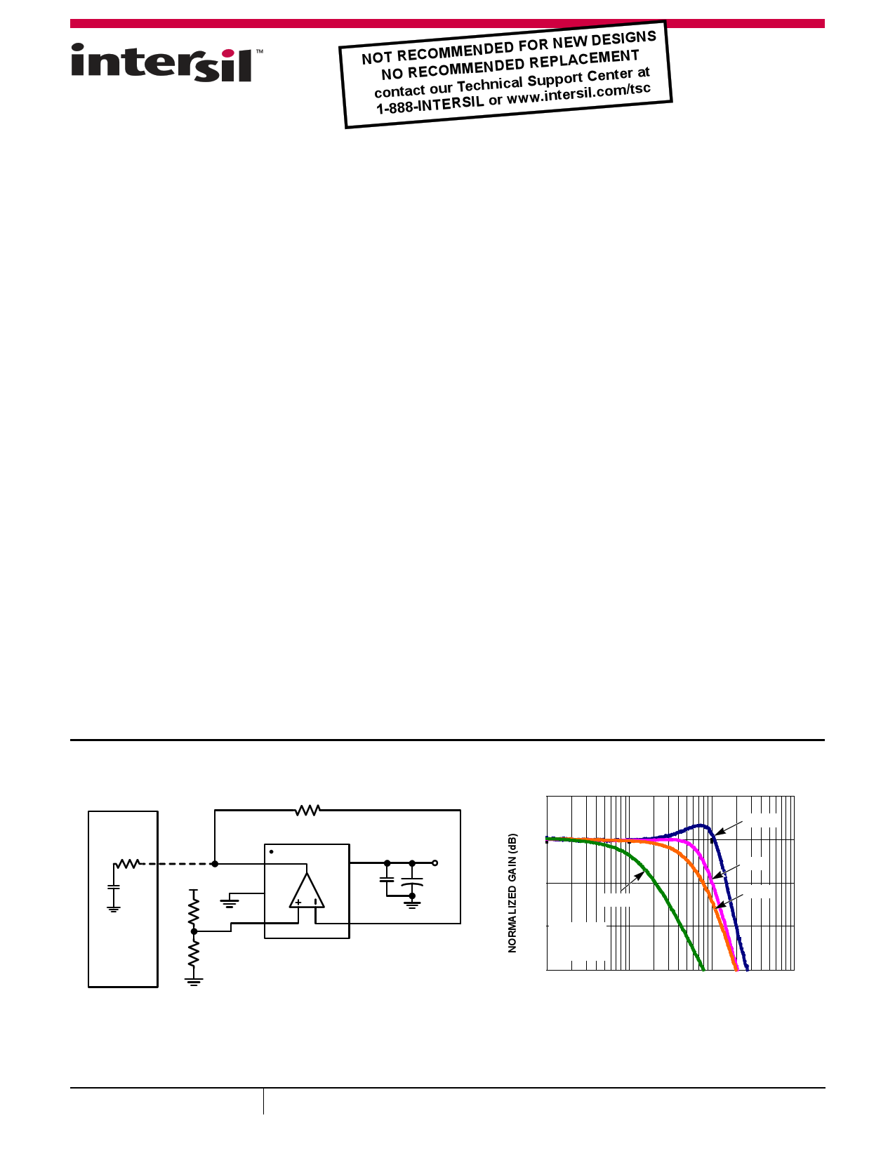
PANEL
LOAD
TFT-LCD
PANEL
+15V
VOUT
VS-
VIN+
0
EL5120T
VS+
0.1µF
+15V
+
4.7µF
VIN-
FIGURE 1. TYPICAL TFT-LCD VCOM APPLICATION
5
0
-5
150Ω
10kΩ
1kΩ
560Ω
-10 VS = ±5V
AV = 1
CL = 8pF
-15
100k
1M 10M
FREQUENCY (Hz)
100M
FIGURE 2. FREQUENCY RESPONSE FOR VARIOUS RL
September 26, 2013
FN6895.1
1
CAUTION: These devices are sensitive to electrostatic discharge; follow proper IC Handling Procedures.
1-888-INTERSIL or 1-888-468-3774 | Copyright Intersil Americas LLC 2012, 2013. All Rights Reserved
Intersil (and design) is a trademark owned by Intersil Corporation or one of its subsidiaries.
All other trademarks mentioned are the property of their respective owners.
1 page 
EL5120T
Electrical Specifications VS+ = +18V, VS- = 0V, RL = 10kΩ to 9V, TA = +25°C, unless otherwise specified.
PARAMETER
DESCRIPTION
CONDITIONS
MIN MAX
(Note 9) TYP (Note 9) UNIT
INPUT CHARACTERISTICS
VOS
TCVOS
IB
RIN
CIN
CMIR
Input Offset Voltage
Average Offset Voltage Drift (Note 6)
Input Bias Current
Input Impedance
Input Capacitance
Common-Mode Input Range
VCM = 9V
VCM = 9V
6 18 mV
6 µV/°C
2 50 nA
1 GΩ
2 pF
-0.5 +18.5 V
CMRR
Common-Mode Rejection Ratio
AVOL
Open Loop Gain
OUTPUT CHARACTERISTICS
For VIN from -0.5V to +18.5V
0.5V VOUT 17.5V
53 78
75 90
dB
dB
VOL Output Swing Low
VOH Output Swing High
ISC Short Circuit Current
IOUT Output Current
POWER SUPPLY PERFORMANCE
IL = -9mA
IL = +9mA
VCM = 9V, Source: VOUT short to VS-,
Sink: VOUT short to VS+
17.85
120
17.88
±200
150
mV
V
mA
±70 mA
(VS+) - (VS-)
IS
PSRR
Supply Voltage Range
Supply Current
Power Supply Rejection Ratio
VCM = 9V, No load
Supply is moved from 4.5V to 19V
4.5 19 V
900 1100 µA
60 75
dB
DYNAMIC PERFORMANCE
SR Slew Rate (Note 7)
1V VOUT 17V, 20% to 80%
12 V/µs
tS Settling to +0.1% (Note 8)
AV = +1, VOUT = 2V step,
RL = 10kΩ, CL = 8pF
500 ns
BW -3dB Bandwidth
RL = 10kΩ, CL = 8pF
12 MHz
GBWP
Gain-Bandwidth Product
AV = -50, RF = 5kΩRG = 100Ω
RL = 10kΩ, CL = 8pF
8 MHz
PM Phase Margin
AV = -50, RF = 5kΩRG = 100Ω
RL = 10kΩ, CL = 8pF
50 °
NOTES:
6. Measured over -40°C to +85°C ambient operating temperature range. See the typical TCVOS production distribution shown in the “Typical
Performance Curves” on page 6.
7. Typical slew rate is an average of the slew rates measured on the rising (20% to 80%) and the falling (80% to 20%) edges of the output signal.
8. Settling time measured as the time from when the output level crosses the final value on rising/falling edge to when the output level settles within a
±0.1% error band. The range of the error band is determined by: Final Value(V)±[Full Scale(V)*0.1%]
9. Compliance to datasheet limits is assured by one or more methods: production test, characterization and/or design.
5 FN6895.1
September 26, 2013
5 Page 
EL5120T
Applications Information
Product Description
The EL5120T is a high voltage rail-to-rail input-output amplifier
with low power consumption. The EL5120T is a single amplifier
which exhibits beyond the rail input capability, rail-to-rail output
capability, and is unity gain stable.
The EL5120T features a slew rate of 12V/µs. Also, the device
provides common mode input capability beyond the supply rails,
rail-to-rail output capability, and a bandwidth of 12MHz (-3dB).
This enables the amplifier to offer maximum dynamic range at
any supply voltage.
Operating Voltage, Input and Output
Capability
The EL5120T can operate on a single supply or dual supply
configuration. The EL5120T operating voltage ranges from a
minimum of 4.5V to a maximum of 19V. This range allows for a
standard 5V (or ±2.5V) supply voltage to dip to -10%, or a standard
18V (or ±9V) to rise by +5.5% without affecting performance or
reliability.
The input common-mode voltage range of the EL5120T extends
500mV beyond the supply rails. Also, the EL5120T is immune to
phase reversal. However, if the common mode input voltage
exceeds the supply voltage by more than 0.5V, electrostatic
protection diodes in the input stage of the device begin to conduct.
Even though phase reversal will not occur, to maintain optimal
reliability it is suggested to avoid input overvoltage conditions.
Figure 28 shows the input voltage driven 500mV beyond the
supply rails and the device output swinging between the supply
rails.
The EL5120T output typically swings to within 50mV of positive
and negative supply rails with load currents of ±5mA. Decreasing
load currents will extend the output voltage range even closer to
the supply rails. Figure 29 shows the input and output waveforms
for the device in a unity-gain configuration. Operation is from ±5V
supply with a 10kΩ load connected to GND. The input is a 10VP-P
sinusoid and the output voltage is approximately 9.9VP-P.
Refer to the “Electrical Specifications” table beginning on page 3
for specific device parameters. Parameter variations with
operating voltage, loading and/or temperature are shown in the
“Typical Performance Curves” beginning on page 6.
VS = ±2.5V, TA = +25°C, AV = 1, VIN = 6VP-P, RL = 10kΩ TO GND
OUTPUT
INPUT
100µs/DIV
FIGURE 28. OPERATION WITH BEYOND-THE-RAILS INPUT
VS = ±5V, TA = +25°C, AV = 1, VIN = 10VP-P, RL = 10kΩ TO GND
100µs/DIV
FIGURE 29. OPERATION WITH RAIL-TO-RAIL INPUT AND OUTPUT
Output Current
The EL5120T is capable of output short circuit currents of
200mA (source and sink), and the device has built-in protection
circuitry, which limits the output current to ±200mA (typical).
To maintain maximum reliability, the continuous output current
should never exceed ±70mA. This ±70mA limit is determined by
the characteristics of the internal metal interconnects. Also, see
“Power Dissipation” on page 12 for detailed information on
ensuring proper device operation and reliability for temperature
and load conditions.
Thermal Shutdown
The EL5120T has a built-in thermal protection, which ensures
safe operation and prevents internal damage to the device due to
overheating. When the die temperature reaches +165°C
(typical), the device automatically shuts OFF the outputs by
putting them in a high impedance state. When the die cools by
+15°C (typical), the device automatically turns ON the outputs by
putting them in a low impedance (normal) operating state.
11 FN6895.1
September 26, 2013
11 Page | ||
| Páginas | Total 14 Páginas | |
| PDF Descargar | [ Datasheet EL5120T.PDF ] | |
Hoja de datos destacado
| Número de pieza | Descripción | Fabricantes |
| EL5120 | (EL5x20) 12MHz Rail-to-Rail Input-Output Op Amps | Intersil |
| EL5120T | 12MHz Rail-to-Rail Input-Output Operational Amplifier | Intersil |
| Número de pieza | Descripción | Fabricantes |
| SLA6805M | High Voltage 3 phase Motor Driver IC. |
Sanken |
| SDC1742 | 12- and 14-Bit Hybrid Synchro / Resolver-to-Digital Converters. |
Analog Devices |
|
DataSheet.es es una pagina web que funciona como un repositorio de manuales o hoja de datos de muchos de los productos más populares, |
| DataSheet.es | 2020 | Privacy Policy | Contacto | Buscar |