|
|
|
PDF CDP6402 Data sheet ( Hoja de datos )
| Número de pieza | CDP6402 | |
| Descripción | CMOS Universal Asynchronous Receiver/Transmitter | |
| Fabricantes | GE | |
| Logotipo | ||
Hay una vista previa y un enlace de descarga de CDP6402 (archivo pdf) en la parte inferior de esta página. Total 8 Páginas | ||
|
No Preview Available !
_ _ _ _ _ _ _ _ _ _ _ _ _ _ _ _ _ _ _ _ _ _ _ _ _ _ CMOS Peripherals
CDP6402, CDP6402C
VDD TRC
NC 'PE
GND CLSI
RRD -
RBRe
CLS2
S8S
RBR7
PI
RBR6
CRL
RBR5
T8RS
RBR4
TBRl
RSR3
TeR6
ReR2
T8R5
RBR'
TBR4
PE TeR 3
FE TBR2
DE T8Rl
SFD TRO
RRC
~
TRE
TBRl
OR
RRI
TBRE
MR
TOP VIEW
92CS-34552
TERMINAL ASSIGNMENT
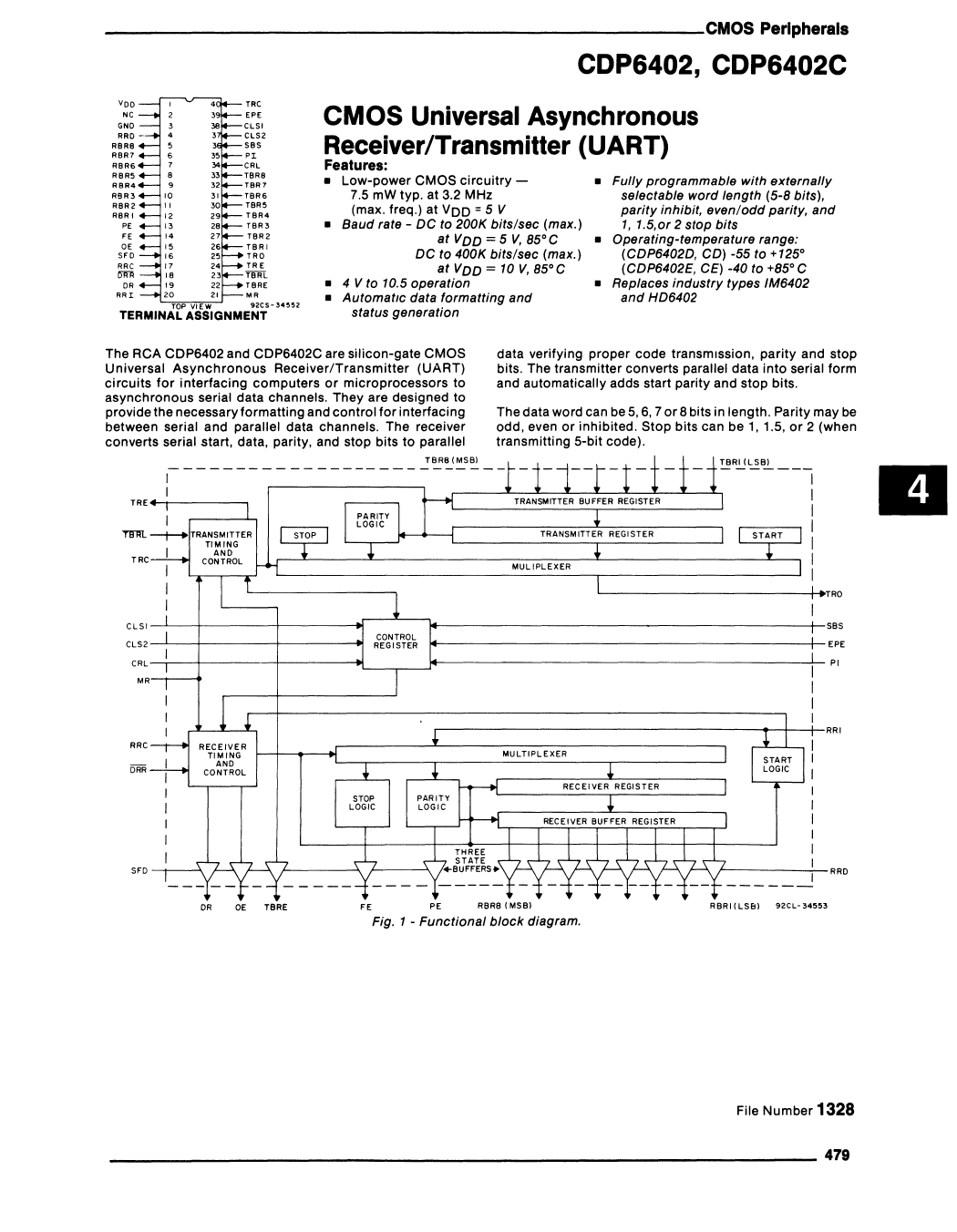
CMOS Universal Asynchronous
Receiver/Transmitter (UART)
Features:
• Low-power CMOS circuitry -
7.5 mW typo at 3.2 MHz
• Fully programmable with externally
selectable word length (5-8 bits),
(max. freq.) at VDD = 5 V
parity inhibit, even/odd parity, and
• Baud rate - DC to 200K bits/sec (max.)
I, 1.5,or 2 stop bits
at VDD = 5 V, 85°C
• Operating-temperature range:
DC to 400K bits/sec (max.)
(CDP6402D, CD) -55 to +125°
at VDD = 10 V,85°C
(CDP6402E, CE) -40 to +85° C
• 4 V to 10.5 operation
• AutomatIc data formatting and
• Replaces industry types IM6402
and HD6402
status generation
The RCA CDP6402 and CDP6402C are silicon-gate CMOS
Universal Asynchronous Receiver/Transmitter (UART)
circuits for interfacing computers or microprocessors to
asynchronous serial data channels. They are designed to
provide the necessary formatting and control for interfacing
between serial and parallel data channels. The receiver
converts serial start, data, parity, and stop bits to parallel
TRE +-r--------,
data verifying proper code transmission, parity and stop
bits. The transmitter converts parallel data into serial form
and automatically adds start parity and stop bits.
The data word can be 5, 6, 7 or 8 bits in length. Parity may be
odd, even or inhibited. Stop bits can be 1, 1.5, or 2 (when
transmitting 5-bit code).
III
TRC
L---------------j-+TRO
ClSI-~--+_-----+_--------~--~~--~----------------------------------------------_t-SBS
CLS2
EPE
CRL--r---t---------t---------~_ __.----~----------------------------------------------_t-Pl
MR
,-----------------------------------------~_+--4__RRI
SFD
DR OE TBRE
FE PE RBRe (MSBI
Fig. 1 - Functional block diagram.
~----------.;__ RRD
RBRI (LSB) 92CL-34553
File Number 1328
479
1 page 
_ _ _ _ _ _ _ _ _ _ _ _ _ _ _ _ _ _ _ _ _ _ _ _ CMOS Peripherals
CDP6402, CDP6402C
Table II - Function Pin Definition (Cont'd)
PIN SYMBOL
DESCRIPTION
23 TBRL A low level on TRANSMITTER BUFFER
REGISTER LOAD transfers data from
inputs TBR1-TBR8 Into the transmitter
buffer register. A low to high transition
on TBRL requests data transfer to the
transmitter register. If the transmitter
register is busy, transfer is automatically
delayed so that the two characters are
transmitted end to end.
24 TRE A high level on TRANSMITTER
REGISTER EMPTY indicates completed
transmission of a character including
stop bits.
25 TRO Character data, start data and stop bits
appear serially at the TRANSMITTER
REGISTER OUTPUT.
26 TBR1 Character data IS loaded into the
TRANSMITTER BUFFER REGISTER via
inputs TBR1-TBR8 For character
formats less than 8-blts, the TBR8, 7,
and 6 Inputs are ignored corresponding
to the programmed word length
27 TBR2
}28 TBR3
29 TBR4
30 TBR5
31 TBR6
32 TBR7
See Pin 28 - TBR1
33 TBR8
PIN SYMBOL
DESCRIPTION
34 CRL A high level on CONTROL REGISTER
LOAD loads the control register.
35 PI' A high level on PARITY INHIBIT inhibits
parity generation, parity checking and
forces PE output low.
36 SBS' A high level on STOP BIT SELECT
selects 1.5 stop bits for a 5 character
format and 2 stop bits for other lengths.
37 CLS2' These inputs program the CHARACTER
LENGTH SELECTED. (CLS1 low CLS2
low 5-bits) (CLS1 high CLS210w 6-bits)
(CLS110w CLS2 high 7-bits) (CLS1 high
CLS2 high 8-bits).
38 CLS1' See Pin 37 - CLS2
39 EPE' When PI IS low, a high level on EVEN
PARITY ENABLE generates and checks
evan parity A low level selects odd
parity
40 TRC The TRANSMITTER REGISTER
CLOCK is 16X the transmit data rate.
'See Table I (Control Word Function)
III
______________________________________________________ 483
5 Page | ||
| Páginas | Total 8 Páginas | |
| PDF Descargar | [ Datasheet CDP6402.PDF ] | |
Hoja de datos destacado
| Número de pieza | Descripción | Fabricantes |
| CDP6402 | CMOS Universal Asynchronous Receiver/Transmitter | GE |
| CDP6402 | CMOS Universal Asynchronous Receiver/Transmitter (UART) | Harris Corporation |
| CDP6402C | CMOS Universal Asynchronous Receiver/Transmitter | GE |
| CDP6402C | CMOS Universal Asynchronous Receiver/Transmitter (UART) | Harris Corporation |
| Número de pieza | Descripción | Fabricantes |
| SLA6805M | High Voltage 3 phase Motor Driver IC. |
Sanken |
| SDC1742 | 12- and 14-Bit Hybrid Synchro / Resolver-to-Digital Converters. |
Analog Devices |
|
DataSheet.es es una pagina web que funciona como un repositorio de manuales o hoja de datos de muchos de los productos más populares, |
| DataSheet.es | 2020 | Privacy Policy | Contacto | Buscar |