|
|
|
PDF UM8254 Data sheet ( Hoja de datos )
| Número de pieza | UM8254 | |
| Descripción | Programmable Interval Timer | |
| Fabricantes | UMC | |
| Logotipo | ||
Hay una vista previa y un enlace de descarga de UM8254 (archivo pdf) en la parte inferior de esta página. Total 15 Páginas | ||
|
No Preview Available !
<l)UMC
UM8254
: : : : : : : : : : : : Programmable Interval Timer
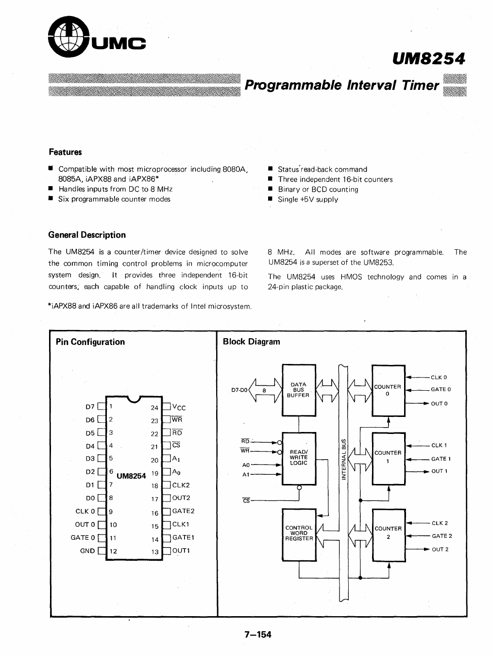
Features
• Compatible with most microprocessor including 8080A,
8085A, iAPX88 and iAPX86*
• Handles inputs from DC to 8 MHz
• Six programmable counter modes
• Status'read-back command
• Three independent 16-bit cpunters
• Binary or BCD counting
• Single +5V supply
General Description
The UM8254 is a counter/timer device designed to solve
the common timing control problems in microcomputer
system design. It provides three independent 16-bit
counters, each capable of handling clock inputs up to
*iAPX88 and iAPX86 are all trademarks of Intel microsystem.
8 MHz. All modes are software programmable. The
UM8254 is a superset of the UM8253.
The UM8254 uses HMOS technology and comes in a
24-pin plastic package.
Pin Configuration
Block Diagram
07
06
05
04
03
02
01
00
ClK 0
aUTO
GATE 0
GNO
Vcc
WR
RO
CS
Al
Ao
ClK2
OUT2
GATE2
ClK1
GATE1
aUT1
07-00
RD'
WR
AO_
A1
READ/
WRITE
lOGIC
cs
ClK 0
GATE 0
OUTO
GATE 1
OUT 1
GATE 2
OUT2
7-154
1 page 
(gUMC
Table 1. Pin Description
Symbol Pin No. Type
Name and Function
D7-DO 1-8 I/O Data: Bi-directional three state data bus
lines, connected to system data bus:
CLKO 9 I Clock 0: Clock Input of Counter O.
OUTO 10 0 Output 0: Output of Counter 0,
GATE 0 11
I Gate 0: Gate Input of Counter O.
GND
12
Ground: Power supply connection.
UM8254
Symbol Pin No. Type
Name and Function
VCC
WR
24 Power +5V power supply connection.
23 I Write Control: This Input is low during
CPU write operations.
RD 22 I Read Control: This input is low during
CPU read operations.
CS 21 I Chip Select: A low on this input enables
the 8254 to respond to RD and Wli
signals. RD and WR are ignored
otherwise.
AI.AO 20-19 I Address: Used to select one of the three
Counters or the Control Word Register
for read or write operations. Normally
connected to the system address bus.
Al Ao
Selects
0 0 Counter 0
0 1 Counter 1
1 0 Counter 2
1 1 Control Word Register
ClK2
18 I Clock 2: Clock Input of Counter 2.
OUT2
17 0 Out 2: Output of Counter 2.
GATE2 16 I Gate 2: Gate Input of Counter 2.
ClK 1 15 I Clock 1: Clock Input of Counter 1.
GATE1 14 I Gate 1: Gate Input of Counter 1.
OUT 1 13 0 Out 1: Output of Counter 1.
Functional Description
General
The UM8254 is a programmable interval timer/counter
designed for use with microcomputer systems. It is a
general purpose, mUlti-timing element that can be treated
as an array of I/O ports in the system software.
The UM8254 solves one of the most common problems in
any microcomputer system, the generation of accurate
time delays under software control. Instead of setting
up timing loops in software, the programmer configures
the UM8254 to match his requirements and programs
one of t:1e counters for the desired delay. After the desired
delay, the UM8254 will interrupt the CPU.. Software
overhead is minimal and variable length delays can easily
be accommodated.
Some of the other counter/timer functions common to
microcomputers which can be implemented with the
UM8254 are:
• R~I time clock
• Event counter
• Digital one-shot
• Programmable rate generator
• Square wave generator
• Binary rate multiplier
• Complex waveform generator
• Complex motor controller
Block Diagram
Data Bus Buffer
This 3-state, bi-directional, 8-bit buffer is used to interface
the UM8254 to the system bus (see Figure 1).
D7·DO
ClK 0 /
GATE 0
OUTO
ClK 1
GATE 1
OUT1
A1
GATE 2
OUT2
Figure 1. Block Diagram Showing Data Bus Buffer and
ReadlWrite Logic Functions
7-158
5 Page 
~UMC
UM8254
If both count and status of a counter are latched, the
first read operation of that counter will return .Iatched
status, regardless of which was latched first. The next
one or two reads (depending on whether the counter is
programmed for one or two t\ .'+: sounts) return latched
count. Subsequent reads return unla+ched count.
CS RD WR Al Ao
0 1 0 00
0 10 01
0 1 0 10
0 1 0 11
0 0 1 00
00 1 01
0 0 1 10
0 0 1 11
1 X X XX
0 1 1 XX
Write into Counter 0
Write into Counter 1
Write into Counter 2
Write Control Word
Read from Counter 0
Read from Counter 1
Read from Counter 2
No-Operation (3-State)
No-Operation (3-State)
No-Operation (3-State)
Figure 12. ReadlWrite Operations Summary
Mode Definitions
The following are defined for use. in describing the
operation of the UM8254.
ClK pulse: a rising edge, then a falling edge, in that
order, of a Counter's ClK input.
trigger: a rising edge of a Counter's GATE input.
Counter loading: the transfer of a count from the c::R
to the CE (refer to the "Functional
Description")
MODE 0: Interrupt on Terminal Count
Mode 0 is typically used for event counting. After the
Control Word is written, OUT is initially low, and will
remain low until the Counter reaches zero. OUT then
goes high and remains high until a new count or a new
Mode 0 Control Word is written into the Counter.
GATE = 1 enables counting; GATE = 0 disables counting.
GATE has no effect on OUT. '
After the Control Word and initial count are written to a
Counter, the initial count will be loaded on the next ClK
pulse. This C lK pulse does not decrement the count, so
for an initial count of N, OUT does not go high untill
N + 1 ClK pulses after the initial count is written.
If a new count is written to the Counter, it will be loaded
on the next ClK pulse and counting will continue from
the new count. If a two-byte count is written, the
following happens:
1) Writing the first byte disables counting. OUT is set
low immediately (no clock pulse required).
2) Writing the second byte allows the new count to be
loaded on the next Cl K pulse.
This allows the counting sequence to by synchronized
by software. Again, OUT does not go high until N + 1
Cl K pulses after the new count of N is written.
If an initial count is written while GATE=O, it will still be
loaded on the next ClK pulse. When GATE goes high,
QUT will go high N ClK pulses later; no ClK pulse is
needed to load the Counter as th is has aIready been done.
cw = 10 LSB = 4,;-_ _ _ _ _ _ _ _ _ __
WR~
ClK
GATE.
OUT ~L.._ _ _ _ _ _ ____'
I N IN I N I N I ~ I~ I ~ I ~ Ig I~~ I~~ I
CW = 10 lSB = 3
WR ~---------------
ClK
GATE
OUT::-l
I N I N I N I N I ~ I~ I .~ I 0 I
r-
I~ I~~ I
CW = 10 lSB = 3
WR
lSB =2
ClK
.....Ir-GATE
OUT
::JI...-___-:--___
I N I N I N I N I 0 I~ I 0 I ~ I 0 I ~ I~~ I
Note: THE FOLLOWING CONVENTIONS APPLY TO ALL MODE TIMING DIAGRAMS:
1. COUNTERS ARE PROGRAMMED FDR BINARY (NOT BCDI COUNTING AND FOR
READINGIWRITING LEAST SIGNIFICANT BYTE(LSBI ONLY
2. THE COUNTER IS ALWAYS SELECTED (CS ALWAYS LDW)
3. CW STANDS FOR "CONTROL WORD". CW=10 MEANS A CONTROL WORD OF 10. HEX
IS WR ITTEN TO THE COUNTER.
4. LSB STANDS FOR "LEAST SIGNIFICANT BYTE" OF COUNT.
5. NUMBERS BELOW DIAGRAMS ARE COUNT VALUES.
THE LOWER NUMBER IS THE LEAST SIGNIFICANT BYTE
THE UPPER NUMBER IS THE MOST SIGNIFICANT BYTE. SINCE THE COUNTER IS
PROGRAMMED TO READIWRITE LSB ONLY. THE MOST SIGNIFICANT BYTE CANNOT
BE READ.
N STANDS FOR AN UNDEFINED COUNT.
VERTICAL LINES SHOW TRANSITIONS BETWEEN COUNT VALUES.
Figure 13. Mode 0
7-164
11 Page | ||
| Páginas | Total 15 Páginas | |
| PDF Descargar | [ Datasheet UM8254.PDF ] | |
Hoja de datos destacado
| Número de pieza | Descripción | Fabricantes |
| UM8250 | Asynchronous Communication Element | UMC |
| UM8250B | Asynchronous Communication Element | UMC Corporation |
| UM8253 | Programmable Interval Timer | UMC |
| UM8253-5 | Programmable Interval Timer | UMC |
| Número de pieza | Descripción | Fabricantes |
| SLA6805M | High Voltage 3 phase Motor Driver IC. |
Sanken |
| SDC1742 | 12- and 14-Bit Hybrid Synchro / Resolver-to-Digital Converters. |
Analog Devices |
|
DataSheet.es es una pagina web que funciona como un repositorio de manuales o hoja de datos de muchos de los productos más populares, |
| DataSheet.es | 2020 | Privacy Policy | Contacto | Buscar |