|
|
|
PDF SAP5S Data sheet ( Hoja de datos )
| Número de pieza | SAP5S | |
| Descripción | Compliant Universal AS-i IC | |
| Fabricantes | IDT | |
| Logotipo | ||
Hay una vista previa y un enlace de descarga de SAP5S (archivo pdf) en la parte inferior de esta página. Total 30 Páginas | ||
|
No Preview Available !
AS-Interface Spec. V3.0
Compliant Universal AS-i IC
SAP51 / SAP5S
Datasheet
Brief Description
The SAP5S/SAP51 is a next-generation CMOS inte-
grated circuit for AS-Interface networks. This low-
level field bus AS-i (Actuator Sensor Interface) was
designed for easy, safe, and cost-effective inter-
connection of sensors, actuators, and switches. It
transports both power and data over the same two-
wire unshielded cable.
The SAP5S/SAP51 is used as part of a master or
slave node and functions as an interface to the
physical bus. It provides the power supply, physical
data transfer, and communication protocol handling.
The SAP5S/SAP51 is fully compliant with the
AS-Interface Complete Specification V3.0. It is func-
tion and pin compatible with the SAP4.1 (AS2702).
The SAP5S/SAP51 can be programmed by the user
to operate in Standard Slave Mode, Safety Mode
(SAP5S only), or Master Mode. The special AS-i
Safety Mode (SAP5S only) assures short response
times regarding security-related events.
All configuration data are stored in an internal
EEPROM that can be easily programmed by a sta-
tionary or handheld programming device.
The SAP5S/SAP51 is optimized for harsh environ-
ments by its special burst protection circuitry and
excellent electromagnetic compatibility.
Features
• Compliant with the AS-Interface Complete
Specification V3.0
• Universal application: slaves, masters, repeaters
• Integrated safety code generator (SAP5S only)
• On-chip electronic inductor: 55mA current
drive capability
• Two LED outputs to support all AS-Interface
Complete Specification V3.0 status indication
modes
• User programmable to operation in Standard
Slave Mode, Safety Mode, or Master Mode
• Supports 5.33 and 16 MHz crystals by
automatic frequency detection
• Data pre-processing functions
• Clock and communication watchdogs
for high system security
Benefits
• Cost savings due to integrated Safety Code
Generator (SAP5S only)
• Special burst protection circuitry
• Excellent electromagnetic compatibility
Physical Characteristics
• Operational temperature range: -25 to +85°C
• SOP16 and SOP20 package
Available Support
• IDT AS-Interface Programmer Kit USB
• IDT SAP5 Evaluation Board V2.0
Related Products
• ASI4U Universal AS-Interface IC
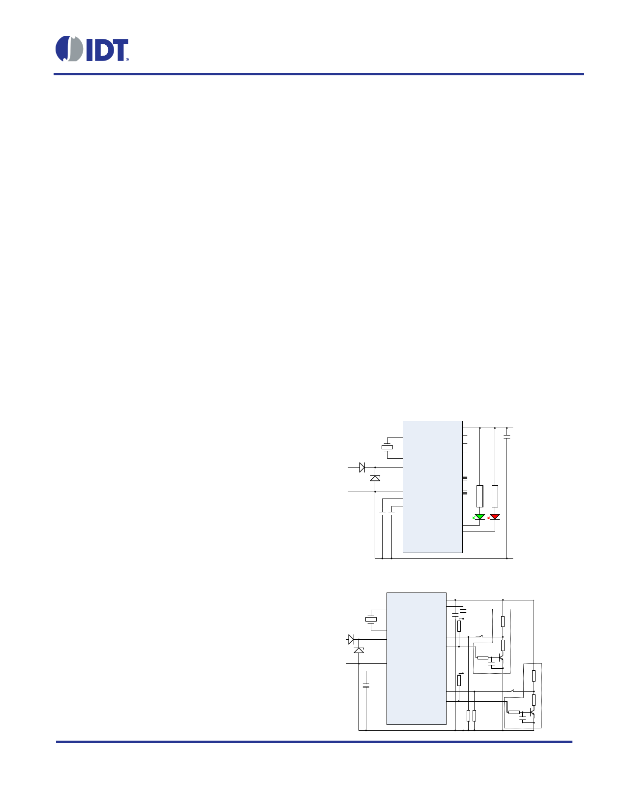
SAP5S/SAP51 Basic Application Circuits
Standard Application
OSC1
UOUT
PFAULT
DSTBn
+24V
OSC2
PSTBn
ASI+ LTGP
D[3:0]
ASI-
LTPN
P[3:0]
CDC
U5R SAP51/
SAP5S
LED1
LED2
+0V
Safety Mode Slave Application
OSC1
UOUT
U5R
ASI+
OSC2
LTGP
D2
D3
SAP5S
ASI- LTPN
CDC
D0
D1
© 2016 Integrated Device Technology, Inc.
1
January 28, 2016
1 page 
SAP51 / SAP5S Datasheet
9.1. Related IDT Documents .......................................................................................................................... 65
9.2. Related Third-Party Documents .............................................................................................................. 65
10 Glossary ......................................................................................................................................................... 66
11 Document Revision History ............................................................................................................................ 66
List of Figures
Figure 3.1
Figure 3.2
Figure 5.1
Figure 5.2
Figure 5.3
Figure 5.4
Figure 5.5
Figure 5.6
Figure 5.7
Figure 5.8
Figure 5.9
Figure 6.1
Figure 6.2
Figure 6.3
Figure 7.1
Figure 7.2
Figure 7.3
Figure 7.4
Figure 7.5
Figure 7.6
Functional Block Diagram ................................................................................................................. 11
Data Path in Master and Repeater Modes ....................................................................................... 14
Basic Receiver Comparator Threshold Set-up Principles ................................................................ 30
Timing Diagram for Parameter Port P[3:0], PSTBn.......................................................................... 31
Timing Diagram for Data Port D[3:0] and DSTBn............................................................................. 32
Principles of Delay Mode Input Filtering – Example for Slave with Address 1HEX ............................ 33
Power-On Behavior (all modes)........................................................................................................ 42
Timing Diagram External Reset via DSTBn ..................................................................................... 43
Safety Mode Data Processing .......................................................................................................... 49
Data Input Voltage Constraints in Safety Mode................................................................................ 50
SAP Package Pin Assignment in Master/Repeater Mode................................................................ 51
Standard Application Circuit, Direction of Data I/O Depends on IO_Code....................................... 57
Safety Mode Application ................................................................................................................... 58
SAP5 Master Mode Application ........................................................................................................ 59
SAP51/SAP5S SOP20 Package Pin Assignment ............................................................................ 61
SAP51 / SAP5S SOP16 Package Pin Assignment .......................................................................... 61
SOP16 Package Outline Dimensions ............................................................................................... 62
SOP20 Package Outline Dimensions ............................................................................................... 63
Package Marking 20-Pin Version ..................................................................................................... 64
Package Marking 16-Pin Version ..................................................................................................... 64
List of Tables
Table 2.1
Table 2.2
Table 2.3
Table 3.1
Table 3.2
Absolute Maximum Ratings ................................................................................................................ 8
Operating Conditions .......................................................................................................................... 9
Crystal Frequency............................................................................................................................... 9
Assignment of Operational Modes.................................................................................................... 13
SAP5 Master Calls and Related Slave Responses .......................................................................... 18
© 2016 Integrated Device Technology, Inc.
5
January 28, 2016
5 Page 
SAP51 / SAP5S Datasheet
3 Basic Functional Description
Note: Unless otherwise noted, the product name SAP5 refers to both the SAP51 and the SAP5S.
The SAP5 is a low-level field bus IC designed for AS-i (Actuator Sensor Interface), which provides a secure
interconnection for sensors, actuators, and switches via a two-wire unshielded cable.
The SAP5 is used as part of a master or slave node and functions as an interface to the physical bus. It provides
the power supply, physical data transfer, and communication protocol handling. The SAP5 can be programmed by
the user to operate in Standard Slave Mode, Safety Mode (SAP5S only), or Master Mode. The special AS-i Safety
Mode (SAP5S only) assures short response times regarding security-related events.
Configuration data are stored in a programmable internal EEPROM.
The SAP5 is optimized for harsh environments by its special burst protection circuitry and excellent electro-
magnetic compatibility.
3.1. Functional Block Diagram
Figure 3.1 Functional Block Diagram
U5R
Power
Supply
Thermal
Protection
CDC Electronic
Inductor
Power
Fail Detector
APF
LTGP
LTGN
Receiver
pos
neg
UART
Transmitter MAN
Main
State
Machine
Param
Offset
I/O
Data
Offset
LED
DSTB
I/O
Output
I/O
PSTB Output
PFAULT Input
UOUT
P[3:0]
D[3:0]
LED1, LED2
DSTBn
PSTBn
PFAULT
OSC1
OSC2
Oscillator
PLL
clk
EEPROM
© 2016 Integrated Device Technology, Inc.
11
January 28, 2016
11 Page | ||
| Páginas | Total 30 Páginas | |
| PDF Descargar | [ Datasheet SAP5S.PDF ] | |
Hoja de datos destacado
| Número de pieza | Descripción | Fabricantes |
| SAP51 | Compliant Universal AS-i IC | IDT |
| SAP51 | Universal Actuator-Sensor Interface IC | ZMDI |
| SAP5S | Compliant Universal AS-i IC | IDT |
| SAP5S | Universal Actuator-Sensor Interface IC | ZMDI |
| Número de pieza | Descripción | Fabricantes |
| SLA6805M | High Voltage 3 phase Motor Driver IC. |
Sanken |
| SDC1742 | 12- and 14-Bit Hybrid Synchro / Resolver-to-Digital Converters. |
Analog Devices |
|
DataSheet.es es una pagina web que funciona como un repositorio de manuales o hoja de datos de muchos de los productos más populares, |
| DataSheet.es | 2020 | Privacy Policy | Contacto | Buscar |