|
|
|
PDF FDPF4N60NZ Data sheet ( Hoja de datos )
| Número de pieza | FDPF4N60NZ | |
| Descripción | MOSFET ( Transistor ) | |
| Fabricantes | Fairchild Semiconductor | |
| Logotipo | ||
Hay una vista previa y un enlace de descarga de FDPF4N60NZ (archivo pdf) en la parte inferior de esta página. Total 10 Páginas | ||
|
No Preview Available !
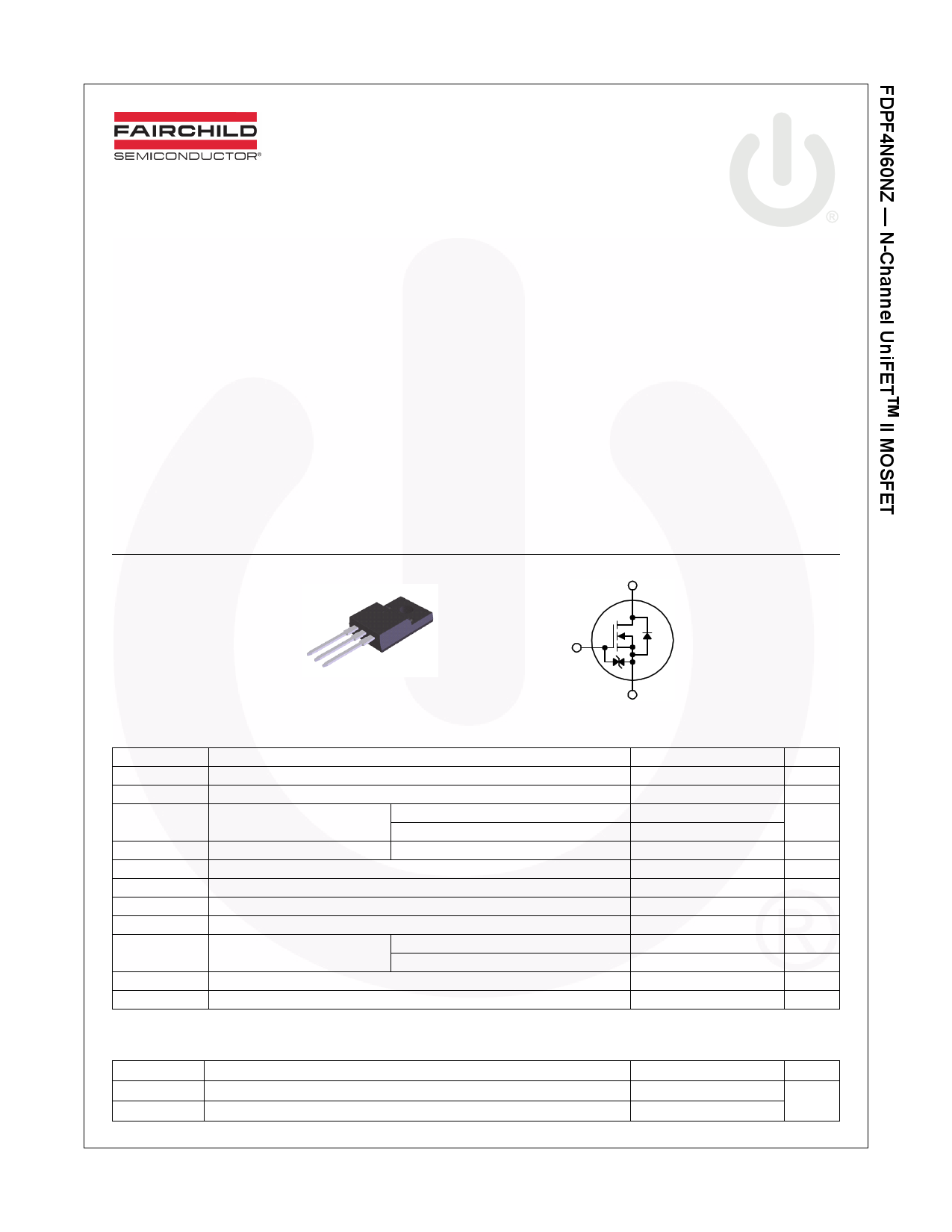
FDPF4N60NZ
N-Channel UniFETTM II MOSFET
600 V, 3.8 A, 2.5 Ω
Features
• RDS(on) = 1.9 Ω (Typ.) @ VGS = 10 V, ID = 1.9 A
• Low Gate Charge (Typ. 8.3 nC)
• Low Crss (Typ. 3.7 pF)
• 100% Avalanche Tested
• Improved dv/dt Capability
• ESD Improved Capability
• RoHS Compliant
Applications
• Consumer Appliances
• Lighting
• Uninterruptible Power Supply
• AC-DC Power Supply
November 2013
Description
UniFETTM II MOSFET is Fairchild Semiconductor’s high voltage
MOSFET family based on advanced planar stripe and DMOS
technology. This advanced MOSFET family has the smallest
on-state resistance among the planar MOSFET, and also pro-
vides superior switching performance and higher avalanche
energy strength. In addition, internal gate-source ESD diode
allows UniFET II MOSFET to withstand over 2kV HBM surge
stress. This device family is suitable for switching power con-
verter applications such as power factor correction (PFC), flat
panel display (FPD) TV power, ATX and electronic lamp bal-
lasts.
D
GDS
TO-220F
G
S
MOSFET Maximum Ratings TC = 25oC unless otherwise noted.
Symbol
Parameter
VDSS
VGSS
ID
IDM
EAS
IAR
EAR
dv/dt
PD
Drain to Source Voltage
Gate to Source Voltage
Drain Current
Drain Current
- Continuous (TC = 25oC)
- Continuous (TC = 100oC)
- Pulsed
Single Pulsed Avalanche Energy
Avalanche Current
Repetitive Avalanche Energy
Peak Diode Recovery dv/dt
Power Dissipation
(TC = 25oC)
- Derate Above 25oC
(Note 1)
(Note 2)
(Note 1)
(Note 1)
(Note 3)
TJ, TSTG
Operating and Storage Temperature Range
TL Maximum Lead Temperature for Soldering, 1/8” from Case for 5 Seconds
*Drain current limited by maximum junction temperature.
Thermal Characteristics
Symbol
RθJC
RθJA
Parameter
Thermal Resistance, Junction to Case, Max.
Thermal Resistance, Junction to Ambient, Max.
©2011 Fairchild Semiconductor Corporation
FDPF4N60NZ Rev. C1
1
FDPF4N60NZ
600
±25
3.8*
2.3*
15*
223.8
3.8
8.9
10
28
0.22
-55 to +150
300
Unit
V
V
A
A
mJ
A
mJ
V/ns
W
W/oC
oC
oC
FDPF4N60NZ
4.5
62.5
Unit
oC/W
www.fairchildsemi.com
1 page 
Typical Performance Characteristics (Continued)
Figure 12. Transient Thermal Response Curve
5
0.5
1 0.2
0.1
0.05
0.1 0.02
0.01
Single pulse
0.01
10-5
10-4
PDM
t1
t2
*Notes:
1. ZθJC(t) = 4.5oC/W Max.
2. Duty Factor, D= t1/t2
3. TJM - TC = PDM * ZθJC(t)
10-3
10-2
10-1
1
t1R, eRcetcatnangguulalarrPPuullssee Durraattiioonn[s[seecc] ]
10 102
©2011 Fairchild Semiconductor Corporation
FDPF4N60NZ Rev. C1
5
www.fairchildsemi.com
5 Page | ||
| Páginas | Total 10 Páginas | |
| PDF Descargar | [ Datasheet FDPF4N60NZ.PDF ] | |
Hoja de datos destacado
| Número de pieza | Descripción | Fabricantes |
| FDPF4N60NZ | MOSFET ( Transistor ) | Fairchild Semiconductor |
| Número de pieza | Descripción | Fabricantes |
| SLA6805M | High Voltage 3 phase Motor Driver IC. |
Sanken |
| SDC1742 | 12- and 14-Bit Hybrid Synchro / Resolver-to-Digital Converters. |
Analog Devices |
|
DataSheet.es es una pagina web que funciona como un repositorio de manuales o hoja de datos de muchos de los productos más populares, |
| DataSheet.es | 2020 | Privacy Policy | Contacto | Buscar |