|
|
|
PDF MAX14827 Data sheet ( Hoja de datos )
| Número de pieza | MAX14827 | |
| Descripción | IO-Link Device Transceiver | |
| Fabricantes | Maxim Integrated | |
| Logotipo | ||
Hay una vista previa y un enlace de descarga de MAX14827 (archivo pdf) en la parte inferior de esta página. Total 30 Páginas | ||
|
No Preview Available !
MAX14827
EVALUATION KIT AVAILABLE
IO-Link Device Transceiver
General Description
The MAX14827 integrates the high-voltage functions
commonly found in industrial sensors, including drivers
and regulators. The MAX14827 features two ultra low-
power drivers with active reverse-polarity protection.
Operation is specified for normal 24V supply voltages
up to 60V. Transient protection is simplified due to high
voltage tolerance allowing the use of micro TVS.
The device features a flexible control interface. Pin-
control logic inputs allow for operation with switching
sensors that do not use a microcontroller. For sensors that
use a microcontroller, an SPI interface is available with
extensive diagnostics. For IO-Link operation, a three-wire
UART interface is provided, allowing interfacing to the
microcontroller UART. Finally, a multiplexed UART/SPI
option allows using one serial microcontroller interface for
shared SPI and UART interfaces.
The device includes on-board 3.3V and 5V linear
regulators for low-noise analog/logic supply rails.
The MAX14827 is available in a (4mm x 4mm) 24-pin
TQFN package and a (2.5mm x 2.5mm) 25-pin wafer-
level package (WLP) and is specified over the extended
-40°C to +125°C temperature range.
Applications
●● Industrial sensors
●● IO-Link sensors and actuators
●● Safety applications
Benefits and Features
●● High Configurability and Integration Reduce SKUs
• IO-Link Compliant Transceiver
• Auxiliary 24V Digital Output and Input
• 2.3Ω (typ) Driver On-Resistance
• Selectable Driver Current: 50mA to 250mA
• SPI or Pin-Control Interface for Configuration and
Monitoring
• Multiplexed SPI/UART Interface Option
• 5V and 3.3V Linear Regulators
• Optional External Transistor Supports Higher
Regulator Load Capability
• Integrated LED Driver
●● Integrated Protection Enables Robust
Communication
• 65V Absolute Maximum Ratings on Interface and
Supply Pins Allows for Flexible TVS Protection
• 9V to 60V Specified Operation
• Glitch Filters for Improved Burst Resilience and
Noise
• Selectable Over-Current Auto-Retry Timing
• Thermal Shutdown Auto-Retry Cycling
• Hot-Plug Supply Protection up to 36V
• Reverse Polarity Protection of All Sensor Interface
Inputs/Outputs
• -40°C to +125°C Operating Temperature Range
Ordering Information appears at end of data sheet.
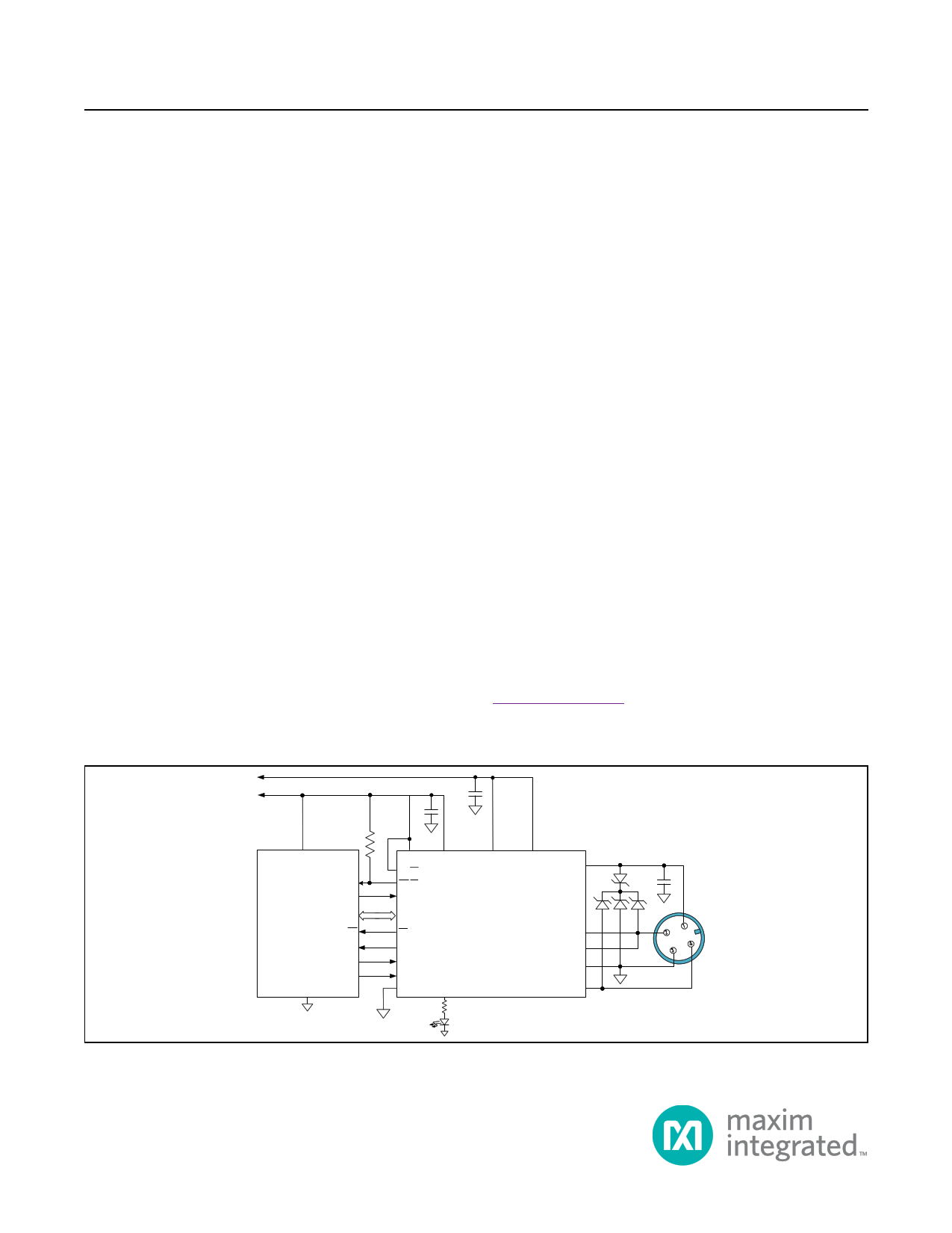
Typical Operating Circuit
5V
3.3V
1µF
1µF
10kΩ
VCC
GPIO
GPO
MICROCONTROLLER
IRQ
RX
TX
RTS
GND
SPI
VL
SPI/PIN
IRQ/OC
LED1IN
V33
WU
RX
TX
TXEN
UARTSEL
LED1
V5 REG
MAX14827
V24
DO
DI
GND
C/Q
0.1µF
L+
DI/DO
1
2
4
3
C/Q
L-
IO-Link is a registered trademark of Profibus User Organization (PNO).
SPI is a trademark of Motorola, Inc.
19-8441; Rev 0; 12/15
1 page 
MAX14827
IO-Link Device Transceiver
DC Electrical Characteristics (continued)
(V24 = 9V to 60V, V5 = 4.5V to 5.5V, VL = 2.5V to 5.5V, VGND = 0V; REG unconnected, all logic inputs at VL or GND; TA = -40°C to
+125°C, unless otherwise noted. Typical values are at V24 = 24V, V5 = 5V, VL = 3.3V, and TA = +25°C, unless otherwise noted.) (Note 2)
PARAMETER
V24 REG Dropout Voltage
REG Open Voltage
SYMBOL
ΔVREG
VREG_OPN
V5 Capacitance
CV5
3.3V LINEAR REGULATOR (V33)
V33 Output Voltage
V33
V33 Load Regulation
V33_LDR
V33 Capacitance
C/Q, DO DRIVER
CV33
Driver On-Resistance
ROH
ROL
Driver Current Limit
ICL
Driver Peak Current
C/Q Leakage Current
ICL_PEAK
ILEAK_CQ
DO Leakage Current
ILEAK_DO
C/Q Output Reverse Current
IREV_CQ
DO Output Reverse Current
IREV_DO
CONDITIONS
V24 = 9V, V5 = 4.5V, IREG = 5mA
V24 = 60V, V5 = 4.5V, no load on REG
Allowed capacitance on V5, REG
connected to V5 (Note 3)
No load on V33
0mA < ILOAD < 30mA
Allowed capacitance on V33, V33
enabled (Note 3)
High-side enabled, V24 = 24V,
CL[10] = 11, ILOAD = -200mA
Low-side enabled, V24 = 24V,
CL[10] = 11, ILOAD = +200mA
SPI/PIN = high,
VDRIVER = (V24 –
3V) or 3V, CL_Dis
=0
CL[10] = 00
CL[10] = 01
CL[10] = 10
CL[10] = 11
SPI/PIN = low,
VDRIVER = (V24 –
3V) or 3V
CLK/TXEN/200MA
= low
CLK/TXEN/200MA
= high
DC current
C/Q driver is disabled (C/Q_Dis = 1), RX
disabled (Rx_Dis = 1), V24 = 24V, (V24 -
65V) ≤ VC/Q ≤ +60V
DO driver is disabled (DO_Dis =1), V24
= 24V, (V24 -65V) ≤ VDO ≤ +60V
C/Q driver enabled and in push-pull
configuration, V24 = 30V, VC/Q = (V24 +
5V) or (VGND - 5V)
DO driver enabled and in push-pull
configuration, V24 = 30V, VDO = (V24 +
5V) or (VGND - 5V)
MIN
10
0.8
3.1
0
0.8
50
100
200
250
100
200
-70
-10
-60
-60
TYP
2.35
13
1
MAX
16
2
UNITS
V
V
µF
3.3 3.5
0.4 0.8
V
%
1 µF
2.65
2.3
65
120
230
290
120
230
4.6
4.45
80
150
275
350
150
275
490
+10
Ω
mA
mA
μA
+10 μA
+1000
μA
+1000
μA
www.maximintegrated.com
Maxim Integrated │ 5
5 Page 
MAX14827
IO-Link Device Transceiver
TXEN
MAX14827
TX
GND
C/Q
3.3nF
5kΩ
TXEN
C/Q
tENH
50%
Figure 3. C/Q Driver Enable High and Disable Low Timing
tDISL
90%
VL
0V
V24
0V
TXEN
C/Q, DI
MAX14827
GND
RX, LI
15pF
C/Q, DI
RX, LI
50%
tPRLH
50%
Figure 4. C/Q and DI Receiver Propagation Delays
50%
tPRHL
50%
V24
0V
VL
0V
www.maximintegrated.com
Maxim Integrated │ 11
11 Page | ||
| Páginas | Total 30 Páginas | |
| PDF Descargar | [ Datasheet MAX14827.PDF ] | |
Hoja de datos destacado
| Número de pieza | Descripción | Fabricantes |
| MAX1482 | Slew-Rate-Limited RS-485 Transceivers | Maxim Integrated |
| MAX14820 | IO-Link Device Transceiver | Maxim Integrated |
| MAX14821 | IO-Link Device Transceiver | Maxim Integrated |
| MAX14824 | IO-Link Master Transceiver | Maxim Integrated |
| Número de pieza | Descripción | Fabricantes |
| SLA6805M | High Voltage 3 phase Motor Driver IC. |
Sanken |
| SDC1742 | 12- and 14-Bit Hybrid Synchro / Resolver-to-Digital Converters. |
Analog Devices |
|
DataSheet.es es una pagina web que funciona como un repositorio de manuales o hoja de datos de muchos de los productos más populares, |
| DataSheet.es | 2020 | Privacy Policy | Contacto | Buscar |