|
|
|
PDF CD22202 Data sheet ( Hoja de datos )
| Número de pieza | CD22202 | |
| Descripción | 5V Low Power DTMF Receiver | |
| Fabricantes | Intersil Corporation | |
| Logotipo | ||
Hay una vista previa y un enlace de descarga de CD22202 (archivo pdf) en la parte inferior de esta página. Total 6 Páginas | ||
|
No Preview Available !
November 2002
c1No®-8nO8taR8c-EItNCOoTOuBErMSRTOMSeLEIcLEhNTonDEriEcwaPDwlRRSwOuE.DipPnUpLteoCArrTCst iECl.MceonEmtNe/rTtsact
CD22202,
CD22203
5V Low Power DTMF Receiver
Features
Description
• Central Office Quality
• No Front End Band Splitting Filters Required
• Single, Low Tolerance, 5V Supply
• Detects Either 12 or 16 Standard DTMF Digits
• Uses Inexpensive 3.579545MHz Crystal for Reference
• Excellent Speech Immunity
• Output in Either 4-Bit Hexadecimal Code or Binary
Coded 2-of-8
• Synchronous or Handshake Interface
• Three-State Outputs
• Excellent Latch-Up Immunity
Part Number Information
PART
NUMBER
CD22202E
CD22203E
TEMP.
RANGE (oC) PACKAGE
0 to 70 18 Ld PDIP
0 to 70 18 Ld PDIP
PKG. NO.
E18.3
E18.3
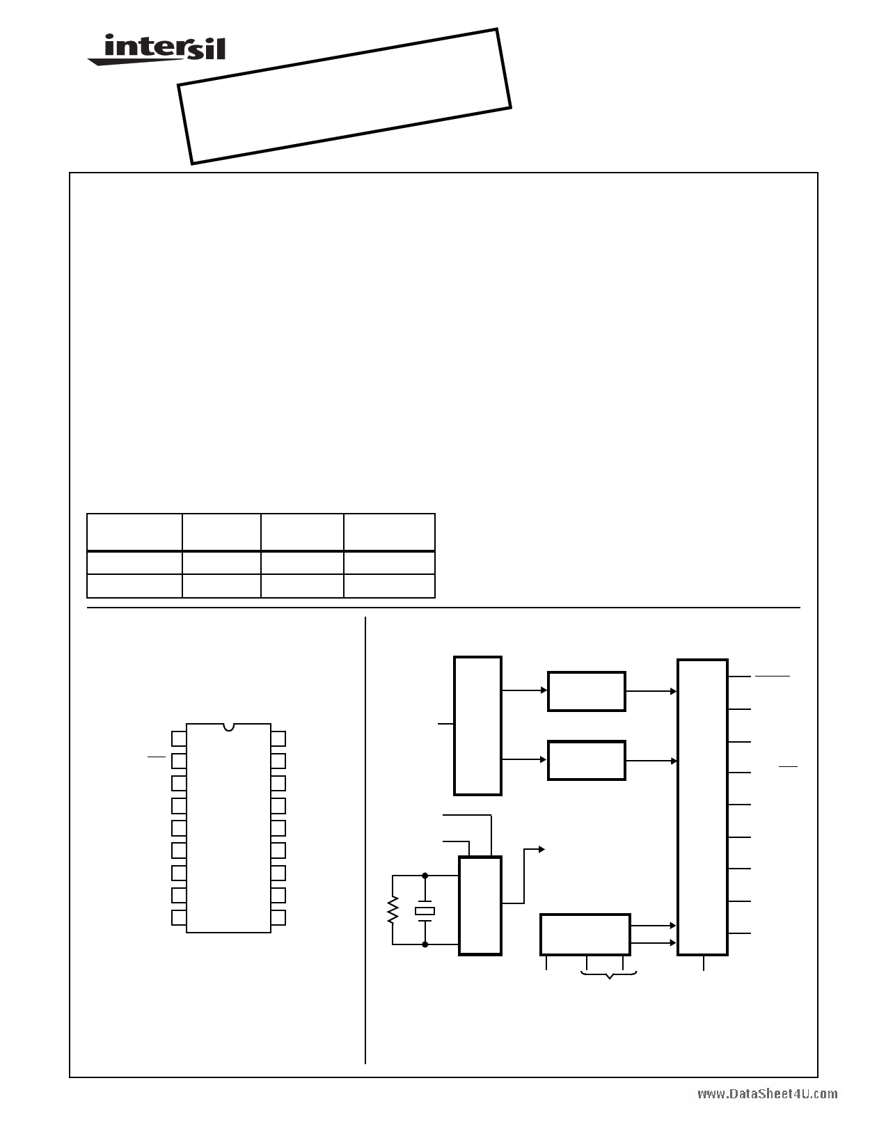
The CD22202 and CD22203 complete dual-tone multiple
frequency (DTMF) receivers detect a selectable group of 12
or 16 standard digits. No front-end pre-filtering is needed.
The only externally required components are an inexpensive
3.579545MHz TV “colorburst’’ crystal (for frequency refer-
ence) and a bias resistor. Extremely high system density is
possible through the use of the clock output of a crystal con-
nected CD22202/CD22203 receiver to drive the time bases
of additional receivers. This is a monolithic integrated circuit
fabricated with low-power, complementary symmetry CMOS
processing. It only requires a single low tolerance power
supply.
The CD22202 and CD22203 employ state-of-the-art circuit
technology to combine the digital and analog functions on
the same CMOS chip using a standard digital semiconductor
process. The analog input is preprocessed by 60Hz reject
and band splitting filters and then hard limited to provide
AGC. Eight Bandpass filters detect the individual tones. The
digital post processor times the tone durations and provides
the correctly coded digital outputs. Outputs interface directly
to standard CMOS circuitry and are three-state enabled to
facilitate bus oriented architectures.
Pinout
CD22202, CD22203
(PDIP)
TOP VIEW
D1 1
HEX/B28 2
EN 3
IN1633 4
VDD
ED (203 ONLY),
NC (202)
VSS
5
6
7
XEN 8
ANALOG IN 9
18 D2
17 D4
16 D8
15 CLRDV
14 DV
13 ATB
12 XIN
11 XOUT
10 VSS
Functional Diagram
9
ANALOG IN
13
ATB
8
XEN
XIN
12
11
XOUT
LOW B/P
FILTERS
HIGH B/P
FILTERS
CHIP
CLOCKS
VOLTAGE
REG./REF.
5
VDD
10 7
VSS
6 ED-203
NC-202
15
CLRDV
14
DV
2
HEX/B28
1
D1
18
D2
17
D4
16
D8
3
EN
4
INI633
CAUTION: These devices are sensitive to electrostatic discharge; follow proper IC Handling Procedures.
1-888-INTERSIL or 321-724-7143 | Intersil (and design) is a trademark of Intersil Americas Inc.
Copyright © Intersil Americas Inc. 2002. All Rights Reserved
1
FN1695.4
1 page 
CD22202, CD22203
into the audio spectrum, so if excessive noise is present
above 28kHz, the simple RC filter shown below may be
used to band limit the incoming signal. The cut off
frequency is 3.9kHz.
NOISY
SIGNAL
270kΩ
0.0015µF
ANALOG
IN
33kΩ
CD22202
CD22203
FIGURE 4. FILTER FOR USE IN EXTREME HIGH FREQUENCY
INPUT NOISE ENVIRONMENT
Noise will also be reduced by placing a grounded trace
around XIN and XOUT pins on the circuit board layout when
using a crystal. It is important to note that XOUT is not
intended to drive an additional device. XIN may be driven
externally; in this case, leave XOUT floating.
Timing Waveforms
TONE BURST 1
tON
ANALOG
INPUT
D1, D2
D4, D8
tD
tSU
tOFF
PAUSE
tR
TONE BURST 2
tH
tCL
PARAMETER
SYMBOL MIN TYP MAX UNITS
Tone Time
For Detection
For Rejection
Pause Time
For Detection
For Rejection
Detect Time
Release Time
Data Setup Time
Data Hold Time
DV Clear Time
CLRDV Pulse Width
ED Detect Time
ED Release Time
Output Enable Time
CL = 50pF, RL = 1kΩ
Output Disable Time
CL = 35pF, RL = 500Ω
Output Rise Time
CL = 50pF
Output Fall Time
CL = 50pF
tON
tON
tOFF
tOFF
tD
tR
tSU
tH
tCL
tPW
tED
tER
-
-
-
-
40 - - ms
- - 20 ms
40 -
-
- - 20
25 - 46
35 50
7- -
4.2 -
5
- 160 250
200 -
-
7 - 22
2 - 18
- 200 300
ms
ms
ms
ms
µs
ms
ns
ns
ms
ms
ns
- 150 200 ns
- 200 300 ns
- 160 250 ns
DV
CLRDV
tPW
tED tER
ED
(NOTE)
NOTE: Early Detect output is available only on the CD22203.
FIGURE 5.
Guard Time
Whenever the DTMF receiver is continually monitoring a
voice channel containing distorted or musical voices or
tones, additional guard time may be added in order to
prevent false decoding. This may be done in software by
verifying that both ED and DV are present simultaneously for
about 55ms. An appropriate guard time should be selected
to balance the fastest expected dialing speed against the
rejection of distorted or musical voices or tones (most
autodialers operate in the 65ms to 75ms range although a
few generate 50ms tones). A hardware guard time circuit is
shown in Figure 6. R3 and R4 should keep the voice
amplitude as low as practical, while R2 and R5 adjust
detection speed.
5
5 Page | ||
| Páginas | Total 6 Páginas | |
| PDF Descargar | [ Datasheet CD22202.PDF ] | |
Hoja de datos destacado
| Número de pieza | Descripción | Fabricantes |
| CD22202 | 5V Low Power DTMF Receiver | Intersil Corporation |
| CD22202E | 5V Low Power DTMF Receiver | Intersil Corporation |
| CD22203 | 5V Low Power DTMF Receiver | Intersil Corporation |
| CD22203E | 5V Low Power DTMF Receiver | Intersil Corporation |
| Número de pieza | Descripción | Fabricantes |
| SLA6805M | High Voltage 3 phase Motor Driver IC. |
Sanken |
| SDC1742 | 12- and 14-Bit Hybrid Synchro / Resolver-to-Digital Converters. |
Analog Devices |
|
DataSheet.es es una pagina web que funciona como un repositorio de manuales o hoja de datos de muchos de los productos más populares, |
| DataSheet.es | 2020 | Privacy Policy | Contacto | Buscar |