|
|
|
PDF VLA546-01R Data sheet ( Hoja de datos )
| Número de pieza | VLA546-01R | |
| Descripción | Hybrid IC for driving IGBT modules | |
| Fabricantes | Isahaya Electronics | |
| Logotipo | ||
Hay una vista previa y un enlace de descarga de VLA546-01R (archivo pdf) en la parte inferior de esta página. Total 7 Páginas | ||
|
No Preview Available !
DESCRIPTION
VLA546 is a hybrid integrated circuit designed for driving
n-channel IGBT modules in any gate-amplifier application.
This device operates as an isolation amplifier for these modules
and provides the required electrical isolation between
the input and output with an opto-coupler.
Recommended IGBT modules:
VCES = 600V series up to 600A class
VCES = 1200V series up to 400A class
VCES = 1700V series up to 400A class
FEATURES
•Electrical isolation between input and output with opto-coupler
(Viso = 4000Vrms for 1minute)
•Two supply driver topology
•Built-in short circuit protection circuit(With a pin for fault out)
•Variable fall time on activity of short circuit protection.
•TTL compatible input interface
HYBRID IC
VLA546-01R
Hybrid IC for driving IGBT modules
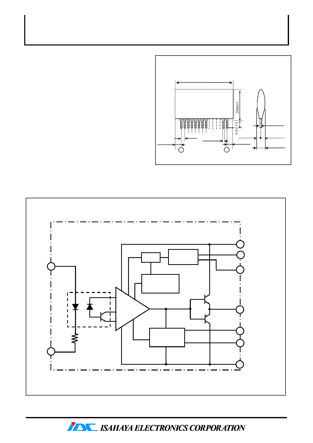
OUTLINE DRAWING
Dimensions : mm
44 MAX
5.5MAX
2.54
1
0.5
+0.15
-0.1
14
6.5 MAX
5.5 MAX
0.25
+-
0.2
0.1
3.0 MAX
8.5 MAX
APPLICATIONS
To drive IGBT modules for inverter or AC servo systems application
BLOCK DIAGRAM
VI + 14
LATCH
DETECT
CIRCUIT
TIMER &
RESET CIRCUIT
INTERFACE
240Ω
VI - 13
OPTO-COUPLER
GATE SHUT-
DOWN CIRCUIT
4 VCC
2 CONTROL PIN
FOR ttrip
1 DETECT
5 VO
8 FAULT OUTPUT
7 CONTROL PIN FOR
FALL TIME
6 VEE
3 pin : Non connection
1 page 
HYBRID IC
VLA546-01R
Hybrid IC for driving IGBT modules
APPLICATION CIRCUIT EXAMPLE
4.7kΩ
・APPLICATION EXAMPLE OF SINGLE
POWER SUPPLY
VIN
14
13
HC04 etc.
8
VLA546
1
2
Ctrip
5
4
100μF
100μF
6
D1
DZ1
30v
RG
VCC
VEE
VIN(5V)
14
13
4.7kΩ
8
1
DZ1
30V
VLA546
RG
5
4
R1 VCC
100μF
D1
f=20kHz
D.F.=50%
VIN=5V
VCC = 15V VEE = 10V
RG=3Ω
Ctrip = 0 ~ 47pF(Rough guide)
D1: Fast recovery diode (trr ≤ 0.2us)
RP1H (SanKen) etc.
6
DZ2 Crev
10V
VCC = 25V
Crev=100μF
R1=2.7kΩ~3.3kΩ
※Don’t input on-sign until the provided (R1×Crev(s)) time
has been exceeded after supplied power to this hybrid IC.
PRECAUTION
(1)Voltage compensate capacitors are expected to be located
as close as possible from the hybrid IC.
・APPLICATION EXAMPLE OF HIGH POWER
(2)D1 requires approximately the same voltage of power modules.
(3)If reverse recovery time of D1 is long, pin1 is applied high voltage.
MODULE
In that case, counterplan for protection which insert a zener
diode between pin 1 and 6 is necessary like above diagram.
4.7kΩ
(4)In case pin 2 is operating, the Ctrip is expected to be wired
as close as possible from pin 2 and pin 4.
(Less than 5cm coming and going)
VIN
14
81
VLA546
2
Ctirp
4
VCC
5
D1
DZ1
30V
RG
13 C1
VEE
6
C2
7 CS
VCC = 15V
VEE=10V
Ctrip=10pF
C1,C2≧100μF(low impedance)
5
5 Page | ||
| Páginas | Total 7 Páginas | |
| PDF Descargar | [ Datasheet VLA546-01R.PDF ] | |
Hoja de datos destacado
| Número de pieza | Descripción | Fabricantes |
| VLA546-01R | Hybrid IC for driving IGBT modules | Isahaya Electronics |
| Número de pieza | Descripción | Fabricantes |
| SLA6805M | High Voltage 3 phase Motor Driver IC. |
Sanken |
| SDC1742 | 12- and 14-Bit Hybrid Synchro / Resolver-to-Digital Converters. |
Analog Devices |
|
DataSheet.es es una pagina web que funciona como un repositorio de manuales o hoja de datos de muchos de los productos más populares, |
| DataSheet.es | 2020 | Privacy Policy | Contacto | Buscar |