|
|
|
PDF BD9326EFJ Data sheet ( Hoja de datos )
| Número de pieza | BD9326EFJ | |
| Descripción | Buck Converter | |
| Fabricantes | ROHM Semiconductor | |
| Logotipo | ||
Hay una vista previa y un enlace de descarga de BD9326EFJ (archivo pdf) en la parte inferior de esta página. Total 23 Páginas | ||
|
No Preview Available !
Datasheet
4.75V to 18V, 2A/3A/4A 1ch
Buck Converter with Integrated FET
BD9325FJ BD9326EFJ BD9327EFJ
General Description
The BD9325FJ, BD9326EFJ and BD9327EFJ are
step-down regulators with built-in low resistance high
side N-Channel MOSFET. These ICs can supply
continuous output current of 2A / 3A / 4A
respectively over a wide input range, and provides
not only fast transient response, but also easy phase
compensation because of current mode control.
Features
Low ESR Output Ceramic Capacitors are Available
Low Standby Current during Shutdown Mode
Feedback Voltage
0.9V ± 1.5%(Ta=25°C)
0.9V ± 3.0%(Ta=-25°C to +85°C)
Protection Circuit:
Under Voltage Protection
Thermal Shutdown
Over-Current Protection
Key Specifications
Input Voltage Range:
Output Current
BD9327EFJ :
BD9326EFJ:
BD9325FJ:
Switching Frequency:
High Side FET ON-Resistance
BD9327EFJ:
BD9326EFJ:
BD9325FJ:
Low Side FET ON-Resistance:
Standby Current:
Operating Temperature Range:
4.75V to 18V
4.0A (Max)
3.0A (Max)
2.0A (Max)
380kHz (Typ)
0.11Ω(Typ)
0.12Ω(Typ)
0.16Ω(Typ)
10Ω(Typ)
80μA (Typ)
-40°C to +85°C
Packages
W(Typ) D(Typ) H(Max)
Applications
Distributed Power System
Pre-Regulator for Linear Regulator
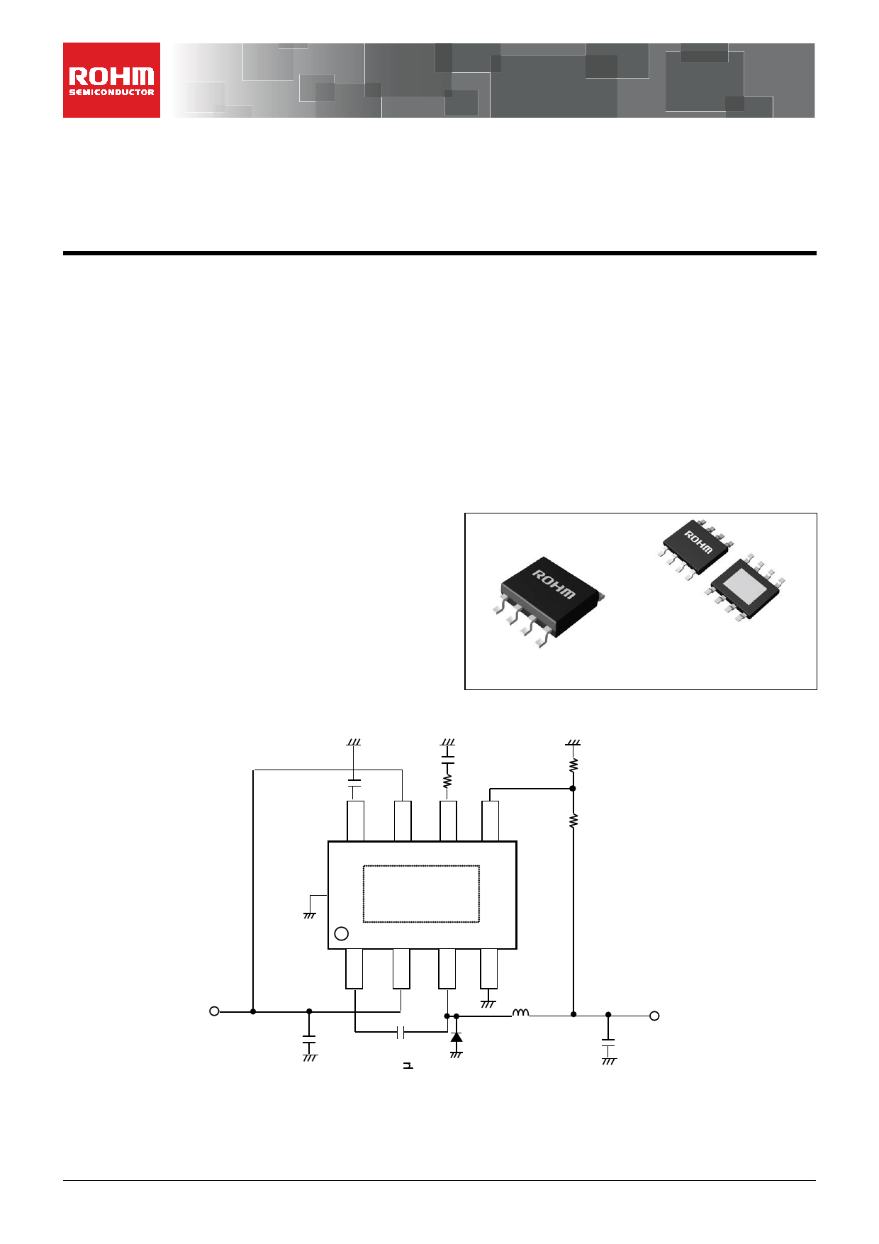
Typical Application Circuit
HTSOP-J8
SOP-J8
4.90mm x 6.00mm x 1.00mm
4.90mm x 6.00mm x 1.65mm
C_SS
0.1μF
C_PC1
3300pF
R_PC
15k
R_DW
10k
R_UP
27k
Thermal Pad
(For BD9326EFJ, BD9327EFJ)
VIN=12V
C_VC1
10μF
L
D 10μH
VOUT = 3.3V
C_CO1
20μF
Figure 1. Typical Application Circuit
〇Product structure : Silicon monolithic integrated circuit
.www.rohm.com
© 2012 ROHM Co., Ltd. All rights reserved.
TSZ22111 • 14 • 001
〇This product has no designed protection against radioactive rays
1/19
TSZ02201-0323AAJ00030-1-2
05.Sep.2014 Rev.002
1 page 
BD9325FJ BD9326EFJ BD9327EFJ
Typical Performance Curves - continued
Ta: [°C]
Figure 8. Hi-Side ON-Resistance
vs Temperature
390
380
370
360
350
340
330
320
-40
-20 0
20 40 60
TTEeMmPpEeRraAtuTrUeR:E[ °:C[C] ]
80
Figure 9. Operating Frequency vs
Temperature
IOUT: [A]
Figure 10. Efficiency vs Output Current
(VIN= 12V VOUT= 3.3V L=10µH)
CSS: [μF]
Figure 11. Soft Start Time vs
Soft Start Capacitor
www.rohm.com
© 2012 ROHM Co., Ltd. All rights reserved.
TSZ22111・15・001
5/19
TSZ02201-0323AAJ00030-1-2
05.Sep.2014 Rev.002
5 Page 
BD9325FJ BD9326EFJ BD9327EFJ
(4) Soft Start Function
COMP
ERRAMP
+
-
2.9V(typ)
70k(typ)
SS
CSS
Figure 23
(5) EN Function
VIN
EN 66kΩ(typ)
The buck converter has an adjustable Soft Start function to
prevent high inrush current during start up.
The soft-start time is set by the external capacitor connected
to SS pin.
The soft start time is given by;
tss = 16200 × CSS [S ]
Please confirm the overshoot of the output voltage and inrush
current when deciding the SS capacitor value.
The EN terminal control the IC’s shut down.
Leaving EN terminal open will shutdown the IC.
To start the IC, EN terminal should be connected to VIN or the
other power source output.
When the EN voltage exceed 1.2V (typ), the IC start
operating.
60kΩ(typ)
Figure 24. The Equivalent Internal Circuit
3. Selecting Application Components
Two high pulsing current flowing loops exist in the buck regulator system.
The first loop, when FET is ON, starts from the input capacitors, to the VIN terminal, to the SW terminal, to the inductor, to
the output capacitors, and then returns to the input capacitor through GND.
The second loop, when FET is OFF, starts from the Schottky diode, to the inductor, to the output capacitor, and then
returns to the Schottky diode through GND.
To reduce the noise and improve the efficiency, please minimize these two loop area.
Especially input capacitor, output capacitor and Schottky diode should be connected to GND plane.
PCB Layout may affect the thermal performance, noise and efficiency greatly. So please take extra care when designing
PCB Layout patterns.
VIN
CIN
L
FET
Di
VOUT
COUT
Figure 25. Current Loop in Buck Regulator System
www.rohm.com
© 2012 ROHM Co., Ltd. All rights reserved.
TSZ22111・15・001
11/19
TSZ02201-0323AAJ00030-1-2
05.Sep.2014 Rev.002
11 Page | ||
| Páginas | Total 23 Páginas | |
| PDF Descargar | [ Datasheet BD9326EFJ.PDF ] | |
Hoja de datos destacado
| Número de pieza | Descripción | Fabricantes |
| BD9326EFJ | Buck Converter | ROHM Semiconductor |
| Número de pieza | Descripción | Fabricantes |
| SLA6805M | High Voltage 3 phase Motor Driver IC. |
Sanken |
| SDC1742 | 12- and 14-Bit Hybrid Synchro / Resolver-to-Digital Converters. |
Analog Devices |
|
DataSheet.es es una pagina web que funciona como un repositorio de manuales o hoja de datos de muchos de los productos más populares, |
| DataSheet.es | 2020 | Privacy Policy | Contacto | Buscar |