|
|
|
PDF A6213 Data sheet ( Hoja de datos )
| Número de pieza | A6213 | |
| Descripción | Constant-Current 3-Ampere PWM Dimmable Buck Regulator LED Driver | |
| Fabricantes | Allegro | |
| Logotipo | ||
Hay una vista previa y un enlace de descarga de A6213 (archivo pdf) en la parte inferior de esta página. Total 17 Páginas | ||
|
No Preview Available !
A6213
Automotive Grade, Constant-Current 3-Ampere
PWM Dimmable Buck Regulator LED Driver
Features and Benefits
• AEC-Q100 qualified
• Supply voltage 6 to 48 V
• True average output current control
• 3.0 A maximum output over operating temperature range
• Cycle-by-cycle current limit
• Integrated MOSFET switch
• Dimming via direct logic input or power supply voltage
• Internal control loop compensation
• Undervoltage lockout (UVLO) and thermal shutdown
protection
• Low power shutdown (1 μA typical)
• Robust protection against:
▫ Adjacent pin-to-pin short
▫ Pin-to-GND short
▫ Component open/short faults
Package 8-pin SOICN with exposed
thermal pad (suffix LJ):
Not to scale
Description
The A6213 is a single IC switching regulator that provides
constant-current output to drive high-power LEDs. It integrates
a high-side N-channel DMOS switch for DC-to-DC step- down
(buck) conversion. A true average current is output using a
cycle-by-cycle, controlled on-time method.
Output current is user-selectable by an external current sense
resistor. Output voltage is automatically adjusted to drive
various numbers of LEDs in a single string. This ensures the
optimal system efficiency.
LED dimming is accomplished by a direct logic input pulse
width modulation (PWM) signal at the enable pin.
The device is provided in a compact 8-pin narrow SOIC package
(suffix LJ) with exposed pad for enhanced thermal dissipation.
It is lead (Pb) free, with 100% matte tin leadframe plating.
Applications:
Automotive lighting
• Daytime running lights
• Front and rear fog lights
• Turn/stop lights
• Map light
• Dimmable interior lights
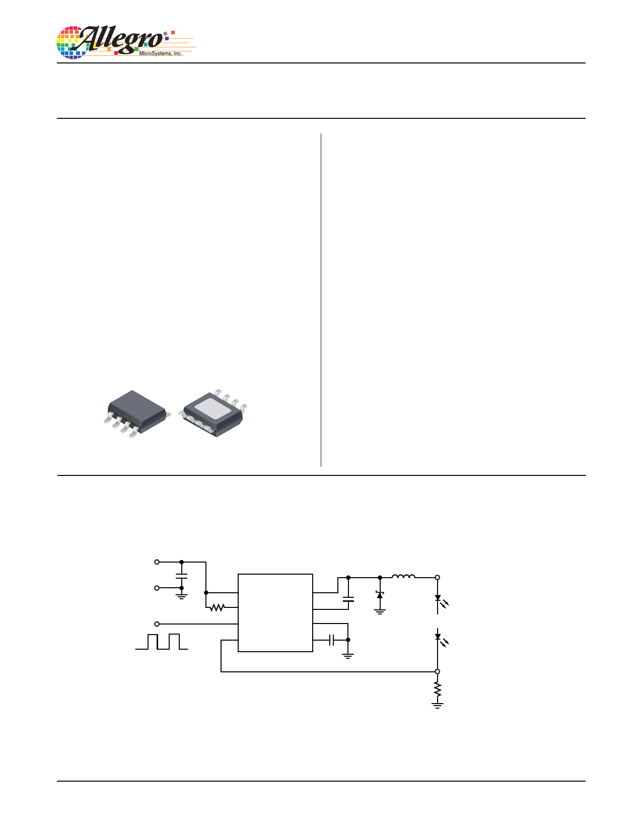
Typical Application Circuit
VIN (6 to 48 V)
GND C1
EN
R1
Enable/PWM Dimming
(100 Hz to 2 kHz)
1
2
VIN
TON
A6213 SW
BOOT
8
7
3 EN
GND 6
4 CS
VCC 5
C4
C5
L1
D1
LED+
LED–
RSENSE
Two different methods of achieving PWM dimming of LED current are shown
A6213-DS
1 page 
A6213
Automotive Grade, Constant-Current 3-Ampere
PWM Dimmable Buck Regulator LED Driver
Characteristic Performance
VIN
VOUT
C1,C2
iLED
C3
VEN
C4
t
Panel 1A. VIN = 19 V
VIN
VIN
VOUT
C1,C2
iLED
C3
VEN
C4
t
Panel 1B. VIN = 24 V
VOUT
C1,C2
iLED
C3
VEN
C4
t
Panel 1C. VIN = 30 V
Figure 1. Startup waveforms from off-state at various input voltages; note that the rise time of the LED current depends on
input/output voltages, inductor value, and switching frequency
• Operating conditions: LED voltage = 15 V, LED current = 1.3 A, R1 = 63.4 kΩ (frequency = 1 MHz in steady state),
VIN = 19 V (panel 1A), 24 V (panel 1B) and 30 V (panel 1C)
• Oscilloscope settings: CH1 (Red) = VIN (10 V/div), CH2 (Blue) = VOUT (10 V/div),
CH3 (Green) = iLED (500 mA/div), CH4 (Yellow) = Enable (5 V/div), time scale = 50 μs/div
Allegro MicroSystems, Inc.
115 Northeast Cutoff
Worcester, Massachusetts 01615-0036 U.S.A.
1.508.853.5000; www.allegromicro.com
5
5 Page 
A6213
Automotive Grade, Constant-Current 3-Ampere
PWM Dimmable Buck Regulator LED Driver
Inductor Selection Chart
The chart in figure 12 summarizes the relationship between LED
current, switching frequency, and inductor value. Based on this
chart: Assuming LED current = 2 A and fSW =1 MHz, then the
minimum inductance required is L = 10 μH in order to keep the
ripple current at 30% or lower. (Note: VOUT = VIN / 2 is the worst
case for ripple current). If the switching frequency is lower, then
either a larger inductance must be used, or the ripple current
requirement has to be relaxed.
2.0
1.8
1.6
1.4
1.2
L=10 μH
1.0
L=15 μH
0.8
L=22 μH
0.6
L=33 μH
0.4
0.2 L=47 μH
0
0.0 0.5 1.0 1.5 2.0 2.5
LED Current, ILED (A)
Figure 12. Inductance selection based on ILED and fSW ; VIN = 24 V,
VOUT = 12 V, ripple current = 30%
3.0
Additional Notes on Ripple Current
• For stability, pick the inductor and switching frequency to
ensure the lowest inductor ripple current percentage is at least
12.5% during worst case (at the lowest VIN).
• There is no hard limit on the highest ripple current percentage
allowed. A 60% ripple current is still acceptable, as long as both
the inductor and LEDs can handle the peak current (average cur-
rent × 1.3 in this case). However, care must be taken to ensure
the valley of the inductor ripple current never drops to zero at the
highest input voltage (which implies a 200% ripple current).
• In general, allowing a higher ripple current percentage enables
lower-inductance inductors to be used, which results in smaller
size and lower cost. The only down-side is the core loss of the
inductor increases with larger ripple currents. But this is typically
a small factor.
• If lower ripple current is required for the LED string, one solu-
tion is to add a small capacitor (such as 2.2 μF) across the LED
string from LED+ to LED– . In this case, the inductor ripple cur-
rent remains high while the LED ripple current is greatly reduced.
Output Filter Capacitor
The A6213 is designed to operate without an output filter capaci-
tor, in order to save cost. Adding a large output capacitor is not
recommended.
VIN
L1 LED+
SW
D1
Iripple
VIN
SW
D1
L1 LED+
C1
Iripple
CS
Vripple
LED–
RSENSE
CS
Vripple
LED–
RSENSE
Without output capacitor:
Ripple current through LED string is
proportional to ripple voltage at CS pin.
With a small capacitor across LED string:
Ripple current through LED string is reduced,
while ripple voltage at CS pin remains high.
Figure 13. Ripple current and voltage, with and without shunt capacitor
Allegro MicroSystems, Inc.
115 Northeast Cutoff
Worcester, Massachusetts 01615-0036 U.S.A.
1.508.853.5000; www.allegromicro.com
11
11 Page | ||
| Páginas | Total 17 Páginas | |
| PDF Descargar | [ Datasheet A6213.PDF ] | |
Hoja de datos destacado
| Número de pieza | Descripción | Fabricantes |
| A6210 | 3A 2MHz Buck-Regulating LED Driver | Allegro MicroSystems |
| A6211 | Constant-Current 3-Ampere PWM Dimmable Buck Regulator LED Driver | Allegro |
| A6213 | Constant-Current 3-Ampere PWM Dimmable Buck Regulator LED Driver | Allegro |
| A6217 | PWM Dimmable Buck Regulator LED Driver | Allegro |
| Número de pieza | Descripción | Fabricantes |
| SLA6805M | High Voltage 3 phase Motor Driver IC. |
Sanken |
| SDC1742 | 12- and 14-Bit Hybrid Synchro / Resolver-to-Digital Converters. |
Analog Devices |
|
DataSheet.es es una pagina web que funciona como un repositorio de manuales o hoja de datos de muchos de los productos más populares, |
| DataSheet.es | 2020 | Privacy Policy | Contacto | Buscar |