|
|
|
PDF DM9095 Data sheet ( Hoja de datos )
| Número de pieza | DM9095 | |
| Descripción | Twisted-Pair Medium Attachment Unit | |
| Fabricantes | Davicom | |
| Logotipo | ||
Hay una vista previa y un enlace de descarga de DM9095 (archivo pdf) en la parte inferior de esta página. Total 21 Páginas | ||
|
No Preview Available !
General Description
The DM9095 twisted-pair Media Attachment Unit
(TPMAU) is designed to allow Ethernet connections
to use existing Twisted-pair wiring plants through an
Ethernet Attachment Unit Interface (AUI). The
DM9095 provides the electrical interface between
the AUI and the twisted-pair wire.
The DM9095’s functions include level-shifted data
pass-through from one transmission media to
another, collision detection, transmitting pre-
distortion
DM9095
Twisted-Pair Medium Attachment Unit
generation, receiving squelch function, selectable
signal-quality-error (SQE) test generation, a link-
integrity strapping option, and automatic correction
of polarity reversal on the twisted pair input. The
DM9095 also includes LED drivers for transmit,
receive, jabber, collision, reversed polarity detect
and link status.
The DM9095 is an advanced CMOS device
available in 28-pin PLCC packages.
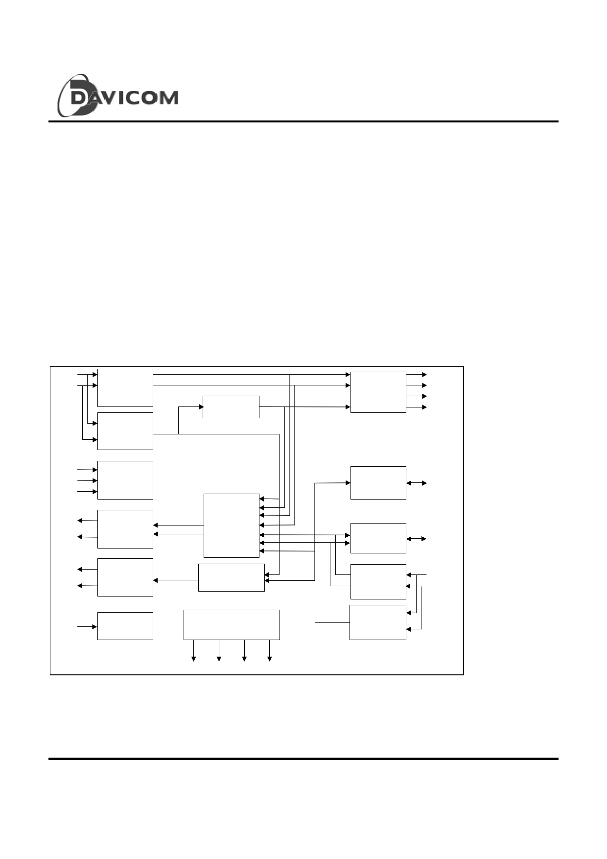
Block Diagram
DO +
DO -
MD0
MD1
MD2
DI +
DI -
CI +
CI -
OSC1
AUI
Data
Receiver
AUI
Data
Squelch
Operation
Mode
Selection
AUI
Current
Driver
Collision
Current
Driver
Crystal
Oscillator
Jabber
Loopback
Control
Collision
Control
LED
Drivers
RLED CLED XLED JLED
TP
Pre-Distortion
Driver
TPO +
DTPO +
DTPO -
TPO-
Link
Integrity
LI-
Auto-Polarity
Detection
TP
Data
Receiver
TP
Data
Squelch
AP
TPI +
TPI -
1 Final
Version: DM9095-DS-F02
August 21, 2000
1 page 
Overview
The DM9095 provides the interface between an AUI and
a TP wire. The receive, transmit, and collision detection
functions of the DM9095 are designed to meet the IEEE
802.3 10BASE-T draft standard. The receive section
transfers 10Mbits/s Manchester-encoded data from the
twisted-pair to the AUI, while the transmit section transfers
data from the AUI cable to the TP wire. The collision-
detection function sends a 10MHz square wave onto the
AUI_CI circuits after sensing data being simultaneously
transmitted and received.
In addition to the these functions, there are three optional
operating functions. Enabling the link-integrity function
causes a pulse to be transmitted in the absence of data
transmission. The Receiver recognized link-integrity
pulses and connects the twisted-pair link. The link-
integrity pin can be configured as an input or as an output.
When the link-integrity pin is configured as an input, the
function is enabled for proper setting. When the link-
integrity pin is configured as an output, the function is
enabled and the status of the link is indicated.
If the heartbeat function is enabled, it allows the SQE-test
sequence to be transmitted to the DTE after every
successful transmission on the TP wire. The option also
DM9095
Twisted-Pair Medium Attachment Unit
enables normal or extended line length to be selected.
When standard TP squelch levels are implemented,
normal line length is used. When the TP squelch
thresholds are lowered, extended line length is used.
The device also contains an auto-polarity function which
can be determined if the receive twisted-pair has been
wired with polarity reversal. If the twisted-pair is wired
with polarity reversal, the device automatically corrects for
this error condition. Also, the auto-polarity function can
be used with an LED to display the polarity of the receive
twisted-pair wire.
When power-down mode is set, the device shuts down,
and the supply current is reduced to less than 10µA. The
DM9095 automatically pulls AUI-DI, AUI_CI, and AUI-DO
into high impedance state if the twisted-pair link is not
connected. The function is used to provide the
Encoder/Decoder chip to use coaxial MAU. The
DM9095 also includes four drivers capable of driving four
LEDs to indicate the status of the receive, transmit,
collision, and jabber functions. Also, when configured
correctly, two additional LEDs can display auto-polarity
and link-integrity status.
5 Final
Version: DM9095-DS-F02
August 21, 2000
5 Page 
Crystal Oscillator
An external TTL-Level clock can be applied to the
OSC1 pin which is crystal oscillator input. A resistor
should be added in series with the clock source to limit
the amplitude of the voltage swing seen by the pin.
A 500 resistor works well in most cases.
DM9095
Twisted-Pair Medium Attachment Unit
integrity function is enabled. If LI- is connected to
VDD or left floating (internal pull-high), the link
integrity function is disabled. When configured as an
output pin, the pin drives low for link-fail state and
drives high for link-pass state. The output pin can
drive an LED status indicator.
LED Status Functions
The LED drivers require an external resistor in series
with the LED, which is in turn connected to VDD.
The driver pulls the pin low to light the LED and can
sink up to 15mA of drive current from the resistor with
an output impedance of less than 50 . The
DM9095 provides three types LED drivers, as follows.
Output LED Drivers: The LED outputs XLED, RLED,
JLED, and CLED are output LED drivers. These
signals are used for status information only. XLED
drives high when the DM9095 is transmitting a packet.
XLED is not asserted if the DM9095 has detected a
jabber function or is in a link-fail state. RLED drives
high when the DM9095 is receiving a packet. RLED
is not asserted when the DM9095 is in a link-fail state.
JLED drives low when the DM9095 has detected a
jabber condition. CLED drives low when the
DM9095 has detected a collision condition.
Sampled LED Driver: The AP pin is used to set the
configuration of the DM9095 and drive the LED status
indicators. Every 26ms, the pin is configured as an
input pin for 6.5• s. During this time, it is sampled by
the DM9095. Outside the sampling window, the
driver is placed in an output state and used to drive
the LED indicators. AP is driven low to indicate that
a reversed twisted pair has been detected on the
receive circuit and corrected. If AP is tied low,
DM9095 disables the auto-polarity function; when AP
is pulled high externally, the function is enabled.
Input / Output LED Driver: LI-pin is an input/output
pin, depending on the mode selection. When
configured as an input pin, LI-controls the link integrity
test option. If LI- is connected to GND, the link
Mode MD0
00
10
20
30
41
51
61
71
MD1
0
0
1
1
0
0
1
1
MD2
0
1
0
1
0
1
0
1
Heartbeat
No
No
No
Yes
Yes
Yes
Power
There are six power connections to the DM9095,
including three VDD and three GND connections.
Pins 1 and 28 are used for analog supplies, including
squelch circuits, receiver, and the internal delay
circuit. Pins 10 and 14 are used for digital circuits,
the I/O buffer, the control logic for analog circuits, and
the crystal oscillator circuit. Pins 18 and 23 are used
for the Twisted Pair driver output buffer.
Operating Modes
The mode selection pins are used to select one of
eight operating modes. These modes are
summarized in the table below.
The modes referred to in the table are the following:
z Heartbeat: A Yest means that the heartbeat
function is enabled; A No means the
heartbeat function is disabled.
z Line Length: “Extended” indicates that TP receive
squelch thresholds have been
lowered to 300mV for use with longer
line lengths; Normal indicates that the
standard 10BASE-T TP receive
squelch threshold of 450mV will be
used.
z LI-: The LI- pin can be configured to be an input
pin, whereby the link-integrity function can be
enabled or disabled. The LI- pin can also be
configured as an output pin to indicate the
status of the link, where the link-integrity is
enabled.
Mode Description
Line Length LI-
Application
Extended
I
Long wire TP
Normal
I Normal wire TP
Normal
O LI pin LED output
Poer-down mode
Extended
I
Long wire TP
Normal
I Normal wire TP
Normal
O LI pin LED output
Power-down mode
11 Final
Version: DM9095-DS-F02
August 21, 2000
11 Page | ||
| Páginas | Total 21 Páginas | |
| PDF Descargar | [ Datasheet DM9095.PDF ] | |
Hoja de datos destacado
| Número de pieza | Descripción | Fabricantes |
| DM9095 | Twisted-Pair Medium Attachment Unit | Davicom |
| Número de pieza | Descripción | Fabricantes |
| SLA6805M | High Voltage 3 phase Motor Driver IC. |
Sanken |
| SDC1742 | 12- and 14-Bit Hybrid Synchro / Resolver-to-Digital Converters. |
Analog Devices |
|
DataSheet.es es una pagina web que funciona como un repositorio de manuales o hoja de datos de muchos de los productos más populares, |
| DataSheet.es | 2020 | Privacy Policy | Contacto | Buscar |