|
|
|
PDF XR1009 Data sheet ( Hoja de datos )
| Número de pieza | XR1009 | |
| Descripción | Rail-to-Rail Amplifiers | |
| Fabricantes | Exar | |
| Logotipo | ||
Hay una vista previa y un enlace de descarga de XR1009 (archivo pdf) en la parte inferior de esta página. Total 16 Páginas | ||
|
No Preview Available !
XR1009, XR2009
0.2mA, 35MHz Rail-to-Rail Amplifiers
General Description
The XR1009 (single) and XR2009 (dual) are ultra-low power, low cost,
voltage feedback ampli ers. These ampli ers use only 208μA of supply
current and are designed to operate from a supply range of 2.5V to 5.5V
(±1.25 to ±2.75).The input voltage range extends 300mV below the negative
rail and 1.2V below the positive rail.
The XR1009 and XR2009 offer superior dynamic performance with a
35MHz small signal bandwidth and 27V/μs slew rate. The combination of
low power, high bandwidth, and rail-to-rail performance make the XR1009
and XR2009 well suited for battery-powered communication/ computing
systems.
F E AT U R E S
■ 208μA supply current
■ 35MHz bandwidth
■ Input voltage range with 5V supply:
-0.3V to 3.8V
■ Output voltage range with 5V supply:
0.08V to 4.88V
■ 27V/μs slew rate
■ 21nV/√Hz input voltage noise
■ 13mA linear output current
■ Fully specified at 2.7V and 5V supplies
■ Replaces MAX4281
A P P L I C AT I O N S
■ Portable/battery-powered applications
■ Mobile communications, cell phones,
pagers
■ ADC buffer
■ Active lters
■ Portable test instruments
■ Signal conditioning
■ Medical equipment
■ Portable medical instrumentation
■ Interactive whiteboards
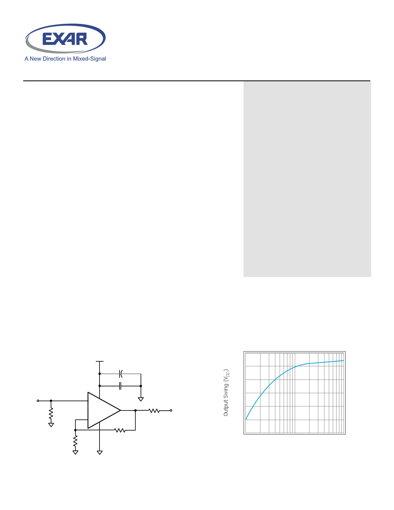
Frequency Response
+2.7
6.8μF
+
In
RIN
0.1μF
+
XR1009
-
Rf Rg
Out
ROUT
Output Swing vs. RL
4.85
4.80
4.75
4.70
4.65
4.60
4.55
1
10
RL (k1)
100
© 2014 Exar Corporation
1 / 16
exar.com/XR1009
Rev 1B
1 page 
XR1009 Pin Con gurations
TSOT-5
OUT 1
5 +Vs
-Vs 2
+-
+IN 3
4 -IN
SOIC-8
NC 1
-IN 2
+IN 3
-
+
-Vs 4
8 NC
7 +Vs
6 OUT
5 NC
XR1009, XR2009
XR1009 Pin Assignments
TSOT-5
Pin No.
1
2
3
4
5
Pin Name
OUT
-VS
+IN
-IN
+VS
Description
Output
Negative supply
Positive input
Negative input
Positive supply
SOIC-8
Pin No.
1
2
3
4
5
6
7
8
Pin Name
NC
-IN
+IN
-VS
NC
OUT
+VS
NC
Description
No Connect
Negative input
Positive input
Negative supply
No Connect
Output
Positive supply
No Connect
XR2009 Pin Con guration
SOIC-8 / MSOP-8
OUT1 1
-IN1 2 -
+IN1 3 +
-Vs 4
8 +Vs
7 OUT2
- 6 -IN2
+ 5 +IN2
XR2009 Pin Assignments
SOIC-8 / MSOP-8
Pin No.
1
2
3
4
5
6
7
8
Pin Name
OUT1
-IN1
+IN1
-VS
+IN2
-IN2
OUT2
+VS
Description
Output, channel 1
Negative input, channel 1
Positive input, channel 1
Negative supply
Positive input, channel 2
Negative input, channel 2
Output, channel 2
Positive supply
© 2014 Exar Corporation
5 / 16
exar.com/XR1009
Rev 1B
5 Page 
Layout Considerations
General layout and supply bypassing play major roles in
high frequency performance. Exar has evaluation boards to
use as a guide for high frequency layout and as an aid in
device testing and characterization. Follow the steps below
as a basis for high frequency layout:
■ Include 6.8µF and 0.1µF ceramic capacitors for power supply
decoupling
■ Place the 6.8µF capacitor within 0.75 inches of the power pin
■ Place the 0.1µF capacitor within 0.1 inches of the power pin
■ Remove the ground plane under and around the part,
especially near the input and output pins to reduce parasitic
capacitance
■ Minimize all trace lengths to reduce series inductances
Refer to the evaluation board layouts below for more
information.
Evaluation Board Information
The following evaluation boards are available to aid in the
testing and layout of these devices:
Evaluation Board #
CEB002
CEB003
CEB006
CEB010
Products
XR1009 in TSOT
XR1009 in SOIC
XR2009 in SOIC
XR2009 in MSOP
Evaluation Board Schematics
Evaluation board schematics and layouts are shown in
Figures 9-18 These evaluation boards are built for dual-
supply operation. Follow these steps to use the board in a
single-supply application:
1. Short -VS to ground.
2. Use C3 and C4, if the -VS pin of the ampli er is not
directly connected to the ground plane.
XR1009, XR2009
Figure 9. CEB002 & CEB003 Schematic
Figure 10. CEB002 Top View
© 2014 Exar Corporation
11 / 16
exar.com/XR1009
Rev 1B
11 Page | ||
| Páginas | Total 16 Páginas | |
| PDF Descargar | [ Datasheet XR1009.PDF ] | |
Hoja de datos destacado
| Número de pieza | Descripción | Fabricantes |
| XR1000 | GaAs MMIC Receiver | Mimix Broadband |
| XR1001 | GaAs MMIC Receiver | Mimix Broadband |
| XR1002 | GaAs MMIC Receiver | Mimix Broadband |
| XR1002-BD | GaAs MMIC Receiver | Mimix Broadband |
| Número de pieza | Descripción | Fabricantes |
| SLA6805M | High Voltage 3 phase Motor Driver IC. |
Sanken |
| SDC1742 | 12- and 14-Bit Hybrid Synchro / Resolver-to-Digital Converters. |
Analog Devices |
|
DataSheet.es es una pagina web que funciona como un repositorio de manuales o hoja de datos de muchos de los productos más populares, |
| DataSheet.es | 2020 | Privacy Policy | Contacto | Buscar |