|
|
|
PDF BM2P053 Data sheet ( Hoja de datos )
| Número de pieza | BM2P053 | |
| Descripción | PWM type DC/DC converter IC Included 650V MOSFET | |
| Fabricantes | ROHM Semiconductor | |
| Logotipo | ||
Hay una vista previa y un enlace de descarga de BM2P053 (archivo pdf) en la parte inferior de esta página. Total 22 Páginas | ||
|
No Preview Available !
Datasheet
AC/DC Drivers
PWM type DC/DC converter IC
Included 650V MOSFET
BM2PXX3 Series
●General
The PWM type DC/DC converter (BM2PXX3) for
AC/DC provide an optimum system for all products
that include an electrical outlet.
BM2PXX3 supports both isolated and non-isolated
devices, enabling simpler design of various types of
low-power electrical converters.
BM2PXX3 built in a HV starter circuit that tolerates
650V, it contributes to low-power consumption.
With current detection resistors as external devices, a
higher degree of design freedom is achieved. Since
current mode control is utilized, current is restricted in
each cycle and excellent performance is demonstrated
in bandwidth and transient response.
The switching frequency is 65 kHz. At light load, the
switching frequency is reduced and high efficiency is
achieved.
A frequency hopping function is also on chip, which
contributes to low EMI.
We can design easily, because BM2PXX3 includes
the switching MOSFET.
●Features
PWM frequency : 65kHz
PWM current mode method
Burst operation when load is light
Frequency reduction function
Built-in 650V start circuit
Built-in 650V switching MOSFET
VCC pin under voltage protection
VCC pin overvoltage protection
SOURCE pin Open protection
SOURCE pin Short protection
SOURCE pin Leading-Edge-Blanking function
Per-cycle over current protection circuit
Soft start
Secondary Over current protection circuit
●Package
DIP7
9.20mm×6.35mm×4.30mm pitch 2.54mm
(Typ.) (Typ.) (Typ.)
(Typ.)
●Basic specifications
Operating Power Supply Voltage Range:
VCC 8.9V to 26.0V DRAIN:~650V
Operating Current: Normal Mode
BM2P013: 0.950mA (Typ.)
BM2P033: 0.775mA (Typ.)
BM2P053: 0.600mA (Typ.)
BM2P093: 0.500mA (Typ.)
Burst Mode: 0.400mA (Typ.)
Oscillation Frequency:
Operating Temperature:
65kHz (Typ.)
- 40 oC to +10 oC
MOSFET ON Resistance:
BM2P013: 1.4Ω (Typ.)
BM2P033: 2.4Ω (Typ.)
BM2P053: 4.0Ω (Typ.)
BM2P093: 8.5Ω (Typ.)
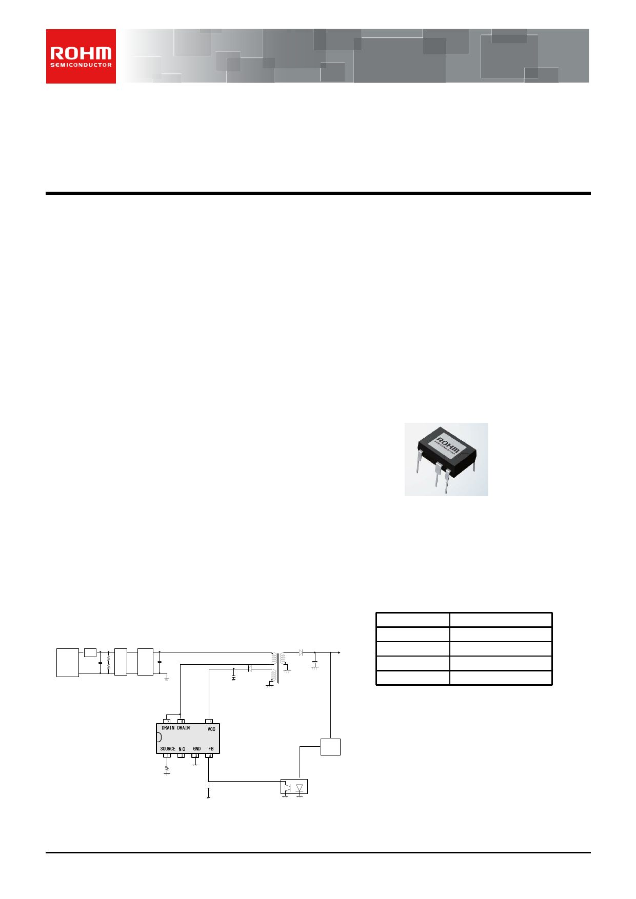
●Application circuit
+ FUSE
AC
85-265Vac
-
Filter
Diode
Bridge
●Applications
AC adapters and household appliances (vacuum
cleaners, humidifiers, air cleaners, air conditioners, IH
cooking heaters, rice cookers, etc.)
●Line up
Product
BM2P013
BM2P033
BM2P053
BM2P093
MOSFET ON Resistor
1.4Ω
2.4Ω
4.0Ω
8.5Ω
ERROR
AMP
Figure 1.Application circuit
○Product structure:Silicon monolithic integrated circuit
.www.rohm.com
© 2012 ROHM Co., Ltd. All rights reserved.
TSZ22111・14・001
○This product is not designed protection against radioactive rays
1/18
TSZ02201-0F2F0A200050-1-2
24. Sep.2015.Rev.007
1 page 
BM2PXX3 Series
●Block Diagram
+ FUSE
AC
Filter
-
Diode
Bridge
Datasheet
VCC OVP
13.5 V
/ 8.2V
+
-
VCC UVLO
+
-
100us
Filter
27. 5V
4.0V
Line Reg
Internal Block
5 67
Starter
12 V Clamp
Circuit
10uA
S
RQ
DRIVER
PWM Control
4.0 V
30k OLP
4 - 64ms
+ Timer
Burst
Comparator
-
+
Current
Limiter
+
-
Leading Edge
Blanking
(typ=250ns)
PWM
Comparator
-
+
MAX
DUTY
+
OSC
(65kHz)
Soft Start
AC Input
Compensation
Frequency
Hopping
Slope
Compensation
1M
1
3
FeedBack
With
Isolation
Figure 3. Block Diagram
www.rohm.com
© 2012 ROHM Co., Ltd. All rights reserved.
TSZ22111・15・001
5/18
TSZ02201-0F2F0A200050-1-2
24. Sep.2015.Rev.007
5 Page 
BM2PXX3 Series
Datasheet
(5) Over Current limiter
BM2PXX3 is built in Over Current limiter per cycle. If the SOURCE pin exceeds a certain voltage, switching is
stopped. It is also built in AC voltage compensation function. This is the function which compensates the maximum
power as the AC voltage’s change by increasing over current limiter with time.
Shown in figure-12, 13, and 14.
Figure 12. No AC voltage compensation function
Figure13. Built-in AC compensation voltage
Primary peak current is decided as the formula below.
Primary peak current: Ipeak = Vcs/Rs + Vdc/Lp*Tdelay
Vcs:Over current limiter voltage internal IC, Rs:Current detection resistance, Vdc input DC voltage, Lp:Primary
inductance,
Tdelay:delay time after detection of over current limiter
Figure 14. Over current limiter voltage
(6)L.E.B period
When the driver MOSFET is turned ON, surge current occurs at each capacitor component and drive current.
Therefore, because SOURCE pin voltage rises temporarily, the detection errors may occur in the over current limiter
circuit.
To prevent detection errors, DRAIN is switched from high to low and the SOURCE signal is masked for 250 ns by the
on-chip LEB (Leading Edge Blanking) function.
www.rohm.com
© 2012 ROHM Co., Ltd. All rights reserved.
TSZ22111・15・001
11/18
TSZ02201-0F2F0A200050-1-2
24. Sep.2015.Rev.007
11 Page | ||
| Páginas | Total 22 Páginas | |
| PDF Descargar | [ Datasheet BM2P053.PDF ] | |
Hoja de datos destacado
| Número de pieza | Descripción | Fabricantes |
| BM2P051 | PWM type DC/DC converter IC Included 650V MOSFET | ROHM Semiconductor |
| BM2P051F | PWM type DC/DC converter IC Included 650V MOSFET | ROHM Semiconductor |
| BM2P052 | PWM type DC/DC converter IC Included 650V MOSFET | ROHM Semiconductor |
| BM2P052F | PWM type DC/DC converter IC Included 650V MOSFET | ROHM Semiconductor |
| Número de pieza | Descripción | Fabricantes |
| SLA6805M | High Voltage 3 phase Motor Driver IC. |
Sanken |
| SDC1742 | 12- and 14-Bit Hybrid Synchro / Resolver-to-Digital Converters. |
Analog Devices |
|
DataSheet.es es una pagina web que funciona como un repositorio de manuales o hoja de datos de muchos de los productos más populares, |
| DataSheet.es | 2020 | Privacy Policy | Contacto | Buscar |