|
|
|
PDF MRF39RA Data sheet ( Hoja de datos )
| Número de pieza | MRF39RA | |
| Descripción | Integrated UHF Receiver | |
| Fabricantes | Microchip | |
| Logotipo | ||
Hay una vista previa y un enlace de descarga de MRF39RA (archivo pdf) en la parte inferior de esta página. Total 30 Páginas | ||
|
No Preview Available !
MRF39RA
Low-Power, Integrated UHF Receiver
Features
• High Sensitivity:
- down to -120 dBm at 1.2 kbps
• High Selectivity:
- 16-Tap FIR channel filter
• Bullet-Proof Front End:
- IIP3 = -18 dBm, IIP2 = +35 dBm, 80 dB
blocking immunity, no image frequency
response
• Low Current:
- Rx = 16 mA, 100 nA register retention
• Constant RF Performance over Voltage Range of
Chip
• FSK Bit Rates up to 300 kbps
• Fully Integrated Synthesizer with a Resolution of
61 Hz
• FSK, GFSK, MSK, GMSK and OOK
Demodulation
• Built-in Bit Synchronizer Performing Clock
Recovery
• Incoming Sync Word Recognition
• 115 dB+ Dynamic Range Received Signal
Strength Indicator (RSSI)
• Automatic RF Sense with Ultra-Fast Automatic
Frequency Control (AFC)
• Packet Engine with CRC, AES-128 Encryption
and 66-Byte First In First Out (FIFO)
• Built-in Temperature Sensor and Low-Battery
Indicator
General Description
The MRF39RA device is a highly integrated RF
receiver capable of operation over a wide frequency
range, including the 433, 868 and 915 MHz
license-free Industry Scientific and Medical (ISM)
frequency bands. Its highly integrated architecture
enables for a minimum of external components while
maintaining maximum design flexibility. All major RF
communication parameters are programmable and
most of these can be dynamically set. The MRF39RA
offers the unique advantage of programmable
narrow-band and wide-band communication modes
without the need of modifying external components.
The MRF39RA is optimized for low-power
consumption while offering high sensitivity and
channelized operation. TrueRF™ technology enables
a low-cost external component count (elimination of the
SAW filter) while still satisfying the European
Telecommunications Standards Institute (ETSI) and
Federal Communications Commission (FCC)
regulations.
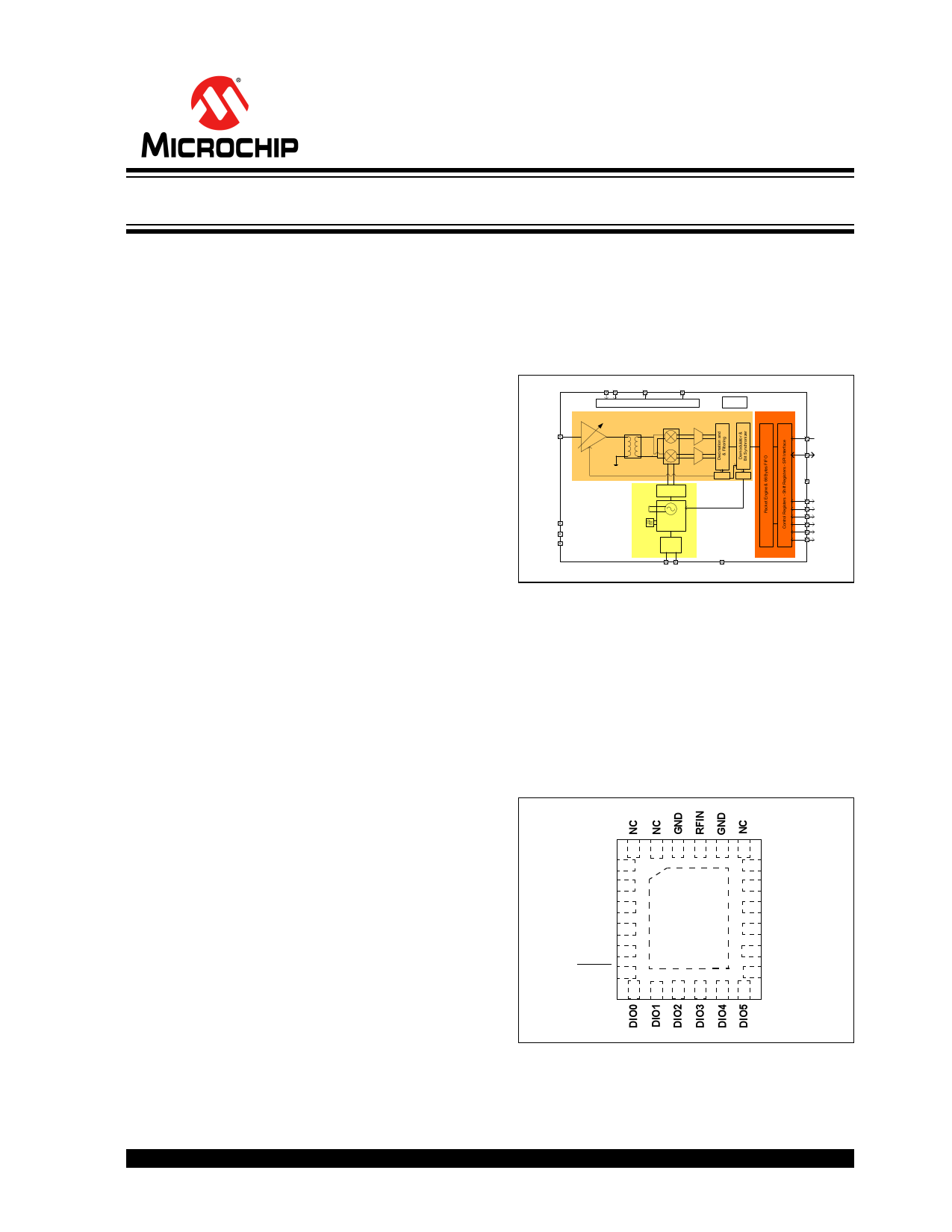
FIGURE 1:
MRF39RA RECEIVER:
LOW-POWER INTEGRATED
UHF RECEIVER
RFIN
VBAT1&2
VR_ANA
VR_DIG
Power Distribution System
LNA
Single to
Differential
Mixers
Modulators
RC
Oscillator
RESET
SPI
Division by
2, 4 or 6
RSSI
AFC
GND
Tank
Inductor
NC
Loop Frac-N PLL
Filter Synthesizer
NC
NC XO
32 MHz
DIO0
DIO1
DIO2
DIO3
DIO4
DIO5
XTAL
GND
Typical Applications
• Automated Meter Reading
• Wireless Sensor Networks
• Home and Building Automation
• Wireless Alarm and Security Systems
• Industrial Monitoring and Control
• Wireless M-Bus
Pin Diagram
FIGURE 2:
24-PIN QFN
24 23 22 21 20 19
VBAT1 1
18 NSS
VR_ANA 2
17 MOSI
VR_DIG 3
16 MISO
XTA 4
15 SCK
XTB 5
14 GND
RESET 6
7
13 VBAT2
8 9 10 11 12
Markets
• Europe: EN 300-220-1
• North America: FCC Part 15.247, 15.249, 15.231
• Narrow Korean and Japanese Bands
2015 Microchip Technology Inc.
DS40001778B-page 1
1 page 
2.0 DEVICE DESCRIPTION
This section describes in detail the architecture of the
MRF39RA low-power, highly integrated receiver.
2.1 Power Supply Strategy
The MRF39RA employs an advanced power supply
scheme, which provides stable operating
characteristics over the full temperature and voltage
range of operation.
The MRF39RA can be powered from any low-noise
voltage source via pins VBAT1 and VBAT2. As
suggested in the reference design, decoupling
capacitors must be connected on VR_DIG and
VR_ANA pins to ensure a correct operation of the
built-in voltage regulators.
2.2 Low Battery Detector
A low battery detector is also included enabling the
generation of an interrupt signal in response to passing
a programmable threshold adjustable through the
RegLowBat register. The interrupt signal can be
mapped to any of the DIO pins through the
programming of RegDioMapping.
2.3 Frequency Synthesis
The LO generation on the MRF39RA is based on a
state-of-the-art fractional-N PLL. The PLL is fully
integrated with automatic calibration.
2.3.1 REFERENCE OSCILLATOR
The crystal oscillator is the main timing reference of the
MRF39RA. It is used as a reference for the frequency
synthesizer and as a clock for the digital processing.
The XO start-up time, TS_OSC, depends on the actual
XTAL being connected on pins XTA and XTB. When
using the built-in sequencer, the MRF39RA optimizes
the start-up time and automatically triggers the PLL
when the XO signal is stable. To manually control the
start-up time, the user must either wait for TS_OSC
max, or monitor the signal CLKOUT, which is only
made available on the output buffer when a stable XO
oscillation is achieved.
An external clock can be used to replace the crystal
oscillator, for instance a tight tolerance TCXO. To do
this, bit 4 at address 0x59 must be set to ‘1’, and the
external clock has to be provided on XTA (pin 4). XTB
(pin 5) must be left open. The peak-peak amplitude of
the input signal must never exceed 1.8V. Consult the
TCXO supplier for an appropriate value of decoupling
capacitor, CD. Figure 2-1 shows the TCXO connection.
MRF39RA
FIGURE 2-1:
TCXO CONNECTION
MRF39RA
XTA XTB
TCXO
32 MHZ
OP
VCC
GND
NC
VCC
CD
2.3.2 CLKOUT OUTPUT
The reference frequency, or a fraction of it, can be
provided on DIO5 (pin 12) by modifying bits ClkOut in
RegDioMapping2. Two typical applications of the
CLKOUT output include:
• Providing a clock output for a companion
processor, thus saving the cost of an additional
oscillator; CLKOUT can be made available in any
operation mode except Sleep mode and is
automatically enabled at Power-on Reset
• Providing an oscillator reference output;
measurement of the CLKOUT signal enables
simple software trimming of the initial crystal
tolerance.
Note:
To minimize the current consumption of
the MRF39RA, ensure that the CLKOUT
signal is disabled when not required.
2015 Microchip Technology Inc.
DS40001778B-page 5
5 Page 
MRF39RA
Table 2-3 lists the accessible channel filter bandwidths (oscillator is mandated at 32 MHz).
TABLE 2-3: AVAILABLE RxBw SETTINGS
RxBwMant
(binary/value)
RxBwExp
(decimal)
RxBw (kHz)
FSK
ModulationType = 00
OOK
ModulationType = 01
10b/24
01b/20
00b/16
10b/24
01b/20
00b/16
10b/24
01b/20
00b/16
10b/24
01b/20
00b/16
10b/24
01b/20
00b/16
10b/24
01b/20
00b/16
10b/24
01b/20
00b/16
10b/24
01b/20
00b/16
7
7
7
6
6
6
5
5
5
4
4
4
3
3
3
2
2
2
1
1
1
0
0
0
2.6
3.1
3.9
5.2
6.3
7.8
10.4
12.5
15.6
20.8
25.0
31.3
41.7
50.0
62.5
83.3
100.0
125.0
166.7
200.0
250.0
333.3
400.0
500.0
1.3
1.6
2.0
2.6
3.1
3.9
5.2
6.3
7.8
10.4
12.5
15.6
20.8
25.0
31.3
41.7
50.0
62.5
83.3
100.0
125.0
166.7
200.0
250.0
2015 Microchip Technology Inc.
DS40001778B-page 11
11 Page | ||
| Páginas | Total 30 Páginas | |
| PDF Descargar | [ Datasheet MRF39RA.PDF ] | |
Hoja de datos destacado
| Número de pieza | Descripción | Fabricantes |
| MRF39RA | Integrated UHF Receiver | Microchip |
| Número de pieza | Descripción | Fabricantes |
| SLA6805M | High Voltage 3 phase Motor Driver IC. |
Sanken |
| SDC1742 | 12- and 14-Bit Hybrid Synchro / Resolver-to-Digital Converters. |
Analog Devices |
|
DataSheet.es es una pagina web que funciona como un repositorio de manuales o hoja de datos de muchos de los productos más populares, |
| DataSheet.es | 2020 | Privacy Policy | Contacto | Buscar |