|
|
|
PDF CD82C284-12 Data sheet ( Hoja de datos )
| Número de pieza | CD82C284-12 | |
| Descripción | Clock Generator and Ready Interface for 80C286 Processors | |
| Fabricantes | Intersil Corporation | |
| Logotipo | ||
Hay una vista previa y un enlace de descarga de CD82C284-12 (archivo pdf) en la parte inferior de esta página. Total 11 Páginas | ||
|
No Preview Available !
82C284
March 1997
Clock Generator and Ready Interface
for 80C286 Processors
Features
• Generates System Clock for 80C286 Processors
• Generates System Reset Output from Schmitt
Trigger Input
- Improved Hysteresis
• Uses Crystal or External Signal for Frequency Source
• Dynamically Switchable between Two Input
Frequencies
• Provides Local READY and MULTIBUS® READY
Synchronization
• Static CMOS Technology
• Single +5V Power Supply
• Available in 18 Lead CerDIP Package
Description
The Intersil 82C284 is a clock generator/driver which
provides clock signals for 80C286 processors and support
components. It also contains logic to supply READY to the
CPU from either asynchronous or synchronous sources and
synchronous RESET from an asynchronous input with
hysteresis.
Ordering Information
PART NUMBER
CD82C284-12
ID82C284-10
ID82C284-12
TEMP. RANGE
0oC to +70oC
-40oC to +85oC
-40oC to +85oC
PACKAGE
PKG.
NO.
18 Ld CERDIP F18.3
18 Ld CERDIP F18.3
18 Ld CERDIP F18.3
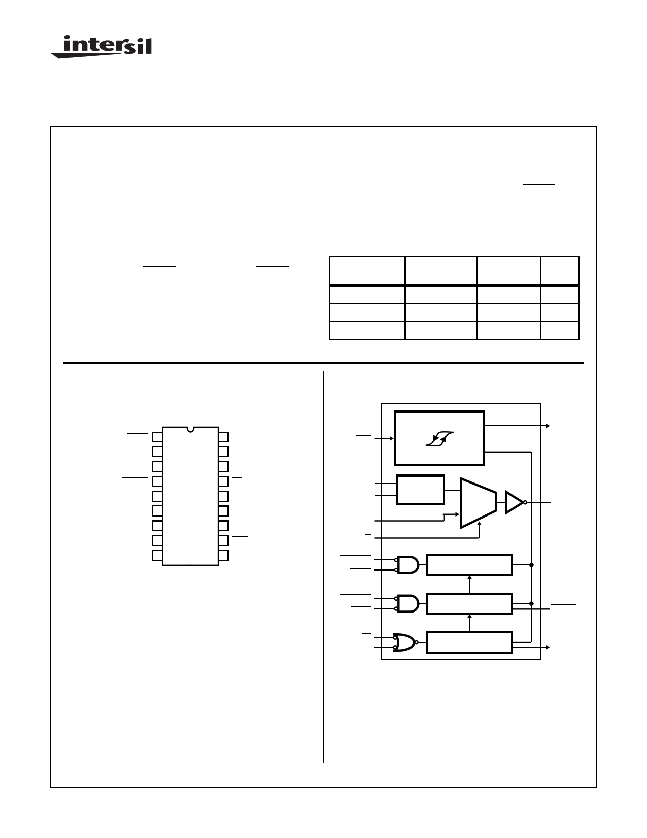
Pinout
82C284 (CERDIP)
TOP VIEW
ARDY 1
SRDY 2
SRDYEN 3
READY 4
EFI 5
F/C 6
X1 7
X2 8
GND 9
18 VCC
17 ARDYEN
16 S1
15 S0
14 NC
13 PCLK
12 RESET
11 RES
10 CLK
Functional Diagram
RES
X1
X2
EFI
F/C
ARDYEN
ARDY
SRDYEN
SRDY
S1
S0
RESET
SYNCHRONIZER
XTAL
OSC
MUX
SYNCHRONIZER
READY LOGIC
PCLK GENERATOR
RESET
CLK
READY
PCLK
CAUTION: These devices are sensitive to electrostatic discharge; follow proper IC Handling Procedures.
http://www.intersil.com or 407-727-9207 | Copyright © Intersil Corporation 1999
MULTIBUS® is a patented Intel bus.
1
File Number 2966.1
1 page 
82C284
LOW to HIGH input transition voltage. As long as the slope of
the RES input voltage remains in the same direction (increas-
ing or decreasing) around the RES input transition voltage, the
RESET output will make a single transition.
VCC
1N914
47Ω
10kΩ
82C284
11
RES
+
10µF
FIGURE 3. TYPICAL RC RES TIMING CIRCUIT
Ready Operation
The 82C284 accepts two ready sources for the system ready
signal which terminates the current bus cycle. Either a synchro-
nous (SRDY) or asynchronous ready (ARDY) source may be
used. Each ready input has an enable (SRDYEN and
ARDYEN) for selecting the type of ready source required to ter-
minate the current bus cycle. An address decoder would nor-
mally select one of the enable inputs.
READY is enabled (LOW), if either SRDY + SRDYEN = 0 or
ARDY + ARDYEN = 0 when sampled by the 82C284 READY
generation logic. READY will remain active for at least two CLK
cycles.
The READY output has an open-drain driver allowing other
ready circuits to be wired with it, as shown in Figure 4. The
READY signal of an 80C286 system requires an external
pull-up resistor. To force the READY signal inactive (HIGH)
at the start of a bus cycle, the READY output floats when
either S1 or S0 are sampled LOW at the falling edge of CLK.
Two system clock periods are allowed for the pull-up resistor
to pull the READY signal to VlH. When RESET is active,
READY is forced active one CLK later (see Waveforms).
7
X1
10
CLK
CLK
VCC
80C286
8 X2
CPU OR
C1
82C284
SUPPORT
COMPONENT
4
6
READY
18
READY
F/C VCC
VCC
DECOUPLING
CAPACITOR
FIGURE 4. RECOMMENDED CRYSTAL AND READY
CONDITIONS
Figure 5 illustrates the operation of SRDY and SRDYEN.
These inputs are sampled on the falling edge of CLK when
S1 and S0 are inactive and PCLK is HIGH. READY is forced
active when both SRDY and SRDYEN are sampled as LOW.
Figure 6 shows the operation of ARDY and ARDYEN These
inputs are sampled by an internal synchronizer at each fall-
ing edge of CLK. The output of the synchronizer is then sam-
pled when PCLK is HIGH. If the synchronizer resolved both
the ARDY and ARDYEN as active, the SRDY and SRDYEN
inputs are ignored. Either ARDY or ARDYEN must be HIGH
at the end of TS, therefore, at least one wait state is required
when using the ARDY and ARDYEN inputs as a basis for
generating READY.
READY remains active until either S1 or S0 are sampled
LOW, or the ready inputs are sampled as inactive.
5
5 Page 
Waveforms (Continued)
CLK
PCLK
F/C
X1
φ1 φ2
t7
t8
82C284
φ1 φ2
φ1 φ2
t27
CLK
PCLK
φ1 φ2 φ1
φ2
φ1 φ2
F/C t7
EFI
t8
t15B
NOTE:
1. This is an asynchronous input. The setup and hold times are required to guarantee the response shown.
FIGURE 12. CLK AS A FUNCTION OF F/C, PCLK, X1, AND EFI DURING DYNAMIC FREQUENCY SWITCHING
All Intersil semiconductor products are manufactured, assembled and tested under ISO9000 quality systems certification.
Intersil products are sold by description only. Intersil Corporation reserves the right to make changes in circuit design and/or specifications at any time without
notice. Accordingly, the reader is cautioned to verify that data sheets are current before placing orders. Information furnished by Intersil is believed to be accurate
and reliable. However, no responsibility is assumed by Intersil or its subsidiaries for its use; nor for any infringements of patents or other rights of third parties which
may result from its use. No license is granted by implication or otherwise under any patent or patent rights of Intersil or its subsidiaries.
For information regarding Intersil Corporation and its products, see web site http://www.intersil.com
Sales Office Headquarters
NORTH AMERICA
Intersil Corporation
P. O. Box 883, Mail Stop 53-204
Melbourne, FL 32902
TEL: (407) 724-7000
FAX: (407) 724-7240
EUROPE
Intersil SA
Mercure Center
100, Rue de la Fusee
1130 Brussels, Belgium
TEL: (32) 2.724.2111
FAX: (32) 2.724.22.05
ASIA
Intersil (Taiwan) Ltd.
Taiwan Limited
7F-6, No. 101 Fu Hsing North Road
Taipei, Taiwan
Republic of China
TEL: (886) 2 2716 9310
FAX: (886) 2 2715 3029
11
11 Page | ||
| Páginas | Total 11 Páginas | |
| PDF Descargar | [ Datasheet CD82C284-12.PDF ] | |
Hoja de datos destacado
| Número de pieza | Descripción | Fabricantes |
| CD82C284-12 | Clock Generator and Ready Interface for 80C286 Processors | Intersil Corporation |
| Número de pieza | Descripción | Fabricantes |
| SLA6805M | High Voltage 3 phase Motor Driver IC. |
Sanken |
| SDC1742 | 12- and 14-Bit Hybrid Synchro / Resolver-to-Digital Converters. |
Analog Devices |
|
DataSheet.es es una pagina web que funciona como un repositorio de manuales o hoja de datos de muchos de los productos más populares, |
| DataSheet.es | 2020 | Privacy Policy | Contacto | Buscar |