|
|
|
PDF CAT3649 Data sheet ( Hoja de datos )
| Número de pieza | CAT3649 | |
| Descripción | 6-Channel LED Driver | |
| Fabricantes | ON Semiconductor | |
| Logotipo | ||
Hay una vista previa y un enlace de descarga de CAT3649 (archivo pdf) en la parte inferior de esta página. Total 13 Páginas | ||
|
No Preview Available !
CAT3649
6-Channel LED Driver with
32 Dimming Levels & PWM
Description
The CAT3649 is a high efficiency fractional charge pump that can
drive up to six LEDs. The inclusion of a 1.33x fractional charge pump
mode increases the device efficiency by up to 10% over traditional
1.5x charge pumps with no added external capacitors.
Low noise input ripple is achieved by operating at a constant
switching frequency which allows the use of small external ceramic
capacitors. The multi−fractional charge pump supports a wide range of
input voltages from 2.4 V to 5.5 V.
The LED current can be adjusted in different ways. The full−scale LED
current is set to 25 mA once the device is enabled. Analog dimming in
32 linear steps is achieved via a 1−wire pulse−dimming input (ADIM).
Further adjustment of the LED current can be done by applying a pulse
width modulation (PWM) signal on the PWM input. The PWM
dimming control is compatible with content adaptive brightness control
(CABC) for a wide range of PWM signal frequency up to 200 kHz.
The CAT3649 can be shut down by holding the ADIM or PWM
input in a logic low condition for greater than 30 ms.
ON Semiconductor’s 1.33x charge pump switching architecture is
patented.
Features
• High Efficiency 1.33x Charge Pump
• Charge Pump: 1x, 1.33x, 1.5x, 2x
• Drives up to 6 LEDs at 25 mA Each
• PWM Dimming 100 Hz to 200 kHz for CABC
• 1−wire EZDim 32 Linear Steps (ADIM)
• Power Efficiency up to 92%
• Low Noise Input Ripple in All Modes
• “Zero” Current Shutdown Mode
• Soft Start and Current Limiting
• Short Circuit Protection
• Thermal Shutdown Protection
• 3 mm x 3 mm, 16−pad TQFN Package
• This Device is Pb−Free, Halogen Free/BFR Free and is RoHS
Compliant
Typical Applications (Note 1)
• LCD Display Backlight
• Cellular Phones
• Digital Still Cameras
• Handheld Devices
1. Typical application circuit with external components is shown in Figure 1.
http://onsemi.com
TQFN−16
HV3 SUFFIX
CASE 510AD
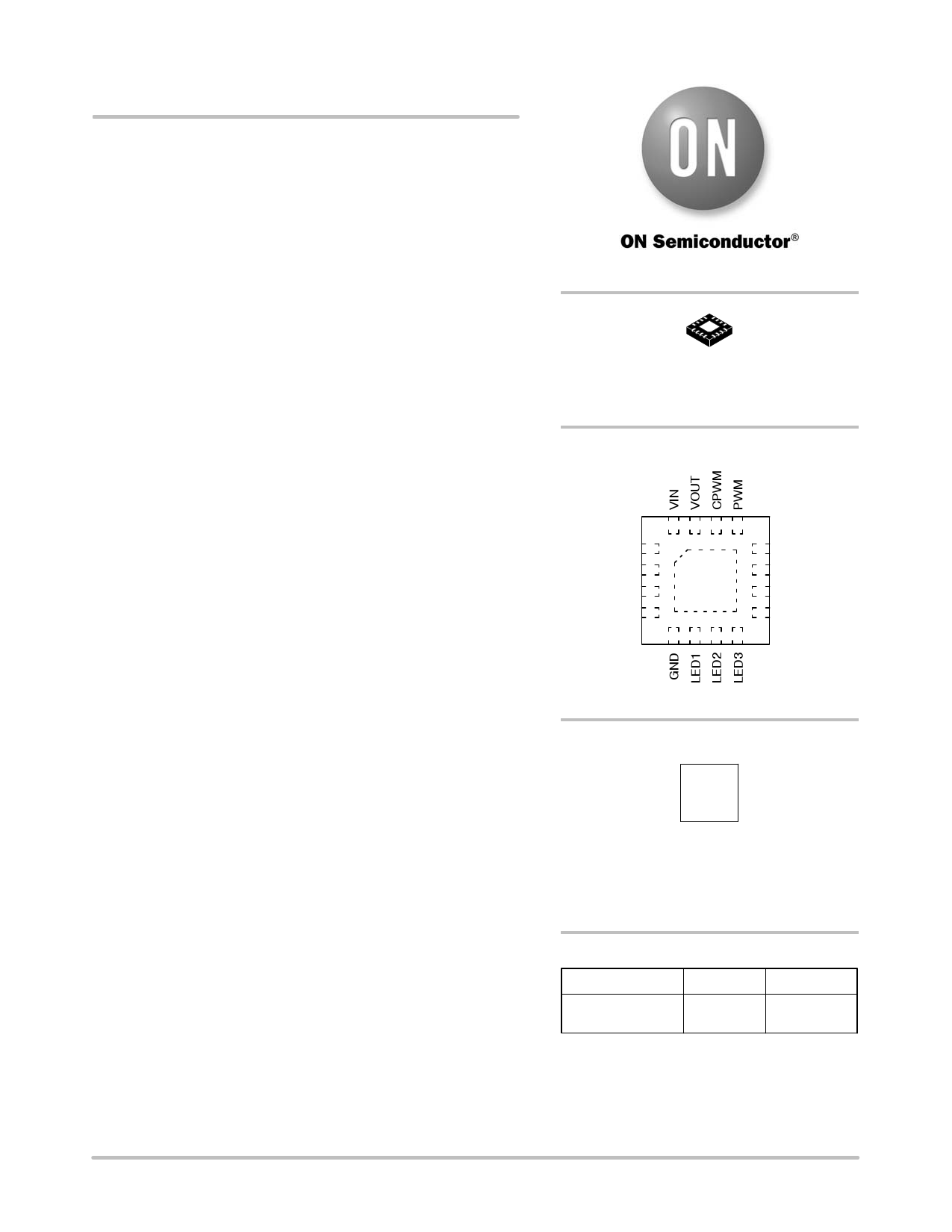
PIN CONNECTIONS
1
C1+
C1−
C2+
C2−
ADIM
LED6
LED5
LED4
(Top View)
MARKING DIAGRAM
JABA
AXXX
YWW
JABA = CAT3649HV3−GT2
A = Assembly Location
XXX = Last Three Digits of Assembly Lot Number
Y = Production Year (Last Digit)
WW = Production Week (Two Digits)
ORDERING INFORMATION
Device
CAT3649HV3−GT2
Package
TQFN−16
(Pb−Free)
Shipping†
2000 /
Tape & Reel
†For information on tape and reel specifications,
including part orientation and tape sizes, please
refer to our Tape and Reel Packaging Specification
Brochure, BRD8011/D.
© Semiconductor Components Industries, LLC, 2014
August, 2014 − Rev. 3
1
Publication Order Number:
CAT3649/D
1 page 
CAT3649
TYPICAL PERFORMANCE CHARACTERISTICS
(VIN = 3.6 V, PWM = VIN, IOUT = 120 mA (6 LEDs at 20 mA), CIN = COUT = C1 = C2 = 1 mF, CPWM = 47 nF,
TAMB = 25°C unless otherwise specified.)
44
VF = 3.3 V
3
2 1x
1.33x
2x
1.5x
3 2x
1.5x
2 1.33x
VIN = 2.6 V
VIN = 2.9 V
VIN = 3.3 V
1
1x
1
VIN = 4.0 V
0
5.0 4.5 4.0 3.5 3.0 2.5
INPUT VOLTAGE (V)
Figure 4. Quiescent Current vs. Input Voltage
0
−40 0
40 80 120
TEMPERATURE (°C)
Figure 5. Quiescent Current vs. Temperature
10
8
6
4
2
0
−2
−4
−6
−8
−10
2.5 3.0 3.5 4.0 4.5 5.0
INPUT VOLTAGE (V)
Figure 6. LED Current Change vs. Input
Voltage
1.3
1.5x Mode
1.2
5.5
1.1
1.0
1.33x, 2x Mode
0.9
0.8
0.7
−40
0 40 80
TEMPERATURE (°C)
Figure 8. Switching Frequency vs.
Temperature
120
10
8
6
4
2
0
−2
−4
−6
−8
−10
−40
12
10
VF = 3.3 V
0 40 80
TEMPERATURE (°C)
Figure 7. LED Current Change vs.
Temperature
2x
120
8
6
1.5x
4
1.33x
2 1x
0
2.0 2.5 3.0 3.5 4.0 4.5 5.0 5.5
INPUT VOLTAGE (V)
Figure 9. Output Resistance vs. Input Voltage
http://onsemi.com
5
5 Page 
CAT3649
Figure 28. ADIM Dimming Timing Diagram (no CPWM, PWM high)
CPWM Filtering Capacitor
The PWM input signal controls the LED current
proportionally to its duty cycle. When the LED driver
operates in PWM dimming mode, the CPWM capacitor
minimizes the LED current ripple. This prevents audio noise
from the LED driver output capacitors as the PWM signal is
converted into a near DC current internally. The PWM input
is a logic input and the amplitude of the PWM signal does
not affect the LED current. An internal 4 mA current source
is charging the CPWM capacitor when the PWM input is high
until it reaches a maximum voltage; see Figure 29 block
diagram. The internal resistor R (150 kW) and external
capacitor CPWM act as a low pass filter with a cut−off
frequency fC = 1/2π R CPWM.
To minimize the ripple current, we recommend the PWM
frequency fPWM to be at least 40 times greater than the
cut−off frequency fC:
fPWM w 40 fC or
(eq. 2)
CPWM
w
(2p
40
R fPWM)
(eq. 3)
For example for fPWM = 1 kHz, the capacitor value is:
CPWM w (2p
40
150 103
103) + 42 nF
(eq. 4)
We recommend a 47 nF capacitor CPWM compatible for
any PWM frequency between 1 kHz and 200 kHz. For PWM
frequency below 1 kHz, the above formula will provide the
recommended capacitor value.
The CPWM capacitor affects the power−up time which is
the time to reach the nominal LED current. The power−up
time (tPU) is proportional to the CPWM capacitor value and
can be calculated as follows.
tPU ^ CPWM 3 105
(eq. 5)
For example, for CPWM = 47 nF, tPU is about 15 ms.
PWM
4 mA
N1
Buffer
R
150 kW
VC G1
Voltage−
controlled
current
source
CPWM
47 nF
I = LED
current
reference
I = g x VC
(for LED at
max current,
g = 0.045)
GND
Figure 29. PWM Circuit Block Diagram
http://onsemi.com
11
11 Page | ||
| Páginas | Total 13 Páginas | |
| PDF Descargar | [ Datasheet CAT3649.PDF ] | |
Hoja de datos destacado
| Número de pieza | Descripción | Fabricantes |
| CAT3643 | 3-Channel Ultra High Efficiency Quad-Mode TM LED Driver | Catalyst Semiconductor |
| CAT3643 | 3-Channel Ultra High Efficiency LED Driver | ON Semiconductor |
| CAT3644 | 4-Channel Ultra High Efficiency Quad-Mode TM LED Driver | Catalyst Semiconductor |
| CAT3644 | 4-Channel Ultra High Efficiency LED Driver | ON Semiconductor |
| Número de pieza | Descripción | Fabricantes |
| SLA6805M | High Voltage 3 phase Motor Driver IC. |
Sanken |
| SDC1742 | 12- and 14-Bit Hybrid Synchro / Resolver-to-Digital Converters. |
Analog Devices |
|
DataSheet.es es una pagina web que funciona como un repositorio de manuales o hoja de datos de muchos de los productos más populares, |
| DataSheet.es | 2020 | Privacy Policy | Contacto | Buscar |