|
|
|
PDF AAT2713 Data sheet ( Hoja de datos )
| Número de pieza | AAT2713 | |
| Descripción | Low Noise Dual 600mA Step-Down Converter | |
| Fabricantes | Advanced Analogic Technologies | |
| Logotipo | ||
Hay una vista previa y un enlace de descarga de AAT2713 (archivo pdf) en la parte inferior de esta página. Total 23 Páginas | ||
|
No Preview Available !
SystemPowerTM
PRODUCT DATASHEET
AAT2713
Low Noise Dual 600mA Step-Down Converter with Synchronization
General Description
The AAT2713 is a high efficiency dual synchronous step-
down converter for applications where power efficiency,
thermal performance and solution size are critical. Input
voltage ranges from 2.7V to 5.5V, making it ideal for
systems powered by single-cell lithium-ion/polymer bat-
teries. The AAT2713 incorporates a unique low noise
architecture which reduces ripple and spectral noise.
Each converter is capable of 600mA output current and
has its own enable pin. Efficiency of the converters is
optimized over full load range. Total no load quiescent
current is 70μA, allowing high efficiency even under light
load conditions.
The integrated power switches are controlled by pulse
width modulation (PWM) with a 1.7MHz typical switching
frequency at full load, which minimizes the size of exter-
nal components. Fixed frequency, low noise operation
can be forced by a logic signal on the MODE pin.
Furthermore, an external clock can be used to synchro-
nize the switching frequency of both converters.
A phase shift pin (PS) is available to operate the two
converters 180° out of phase at heavy load to achieve
low input ripple.
The AAT2713 is available in a Pb-free, thermally
enhanced 16-pin QFN33 package and is specified for
operation over the -40°C to +85°C temperature range.
Features
• VIN Range: 2.7V to 5.5V
• Low Noise Light Load Mode
• Low Ripple PWM Mode
• Output Current:
▪ Channel 1: 600mA
▪ Channel 2: 600mA
• 96% Efficient Step-Down Converter
• Low No Load Quiescent Current
▪ 70μA Total for Both Converters
• Integrated Power Switches
• 100% Duty Cycle
• 1.7MHz Switching Frequency
• Optional Fixed Frequency or External SYNC
• Logic Selectable 180° Phase Shift Between the Two
Converters
• Current Limit Protection
• Automatic Soft-Start
• Over-Temperature Protection
• QFN33-16 Package
• -40°C to +85°C Temperature Range
Applications
• Cellular Phones / Smart Phones
• Digital Cameras
• Handheld Instruments
• Micro Hard Disc Drives
• Microprocessor / DSP Core / IO Power
• PDAs and Handheld Computers
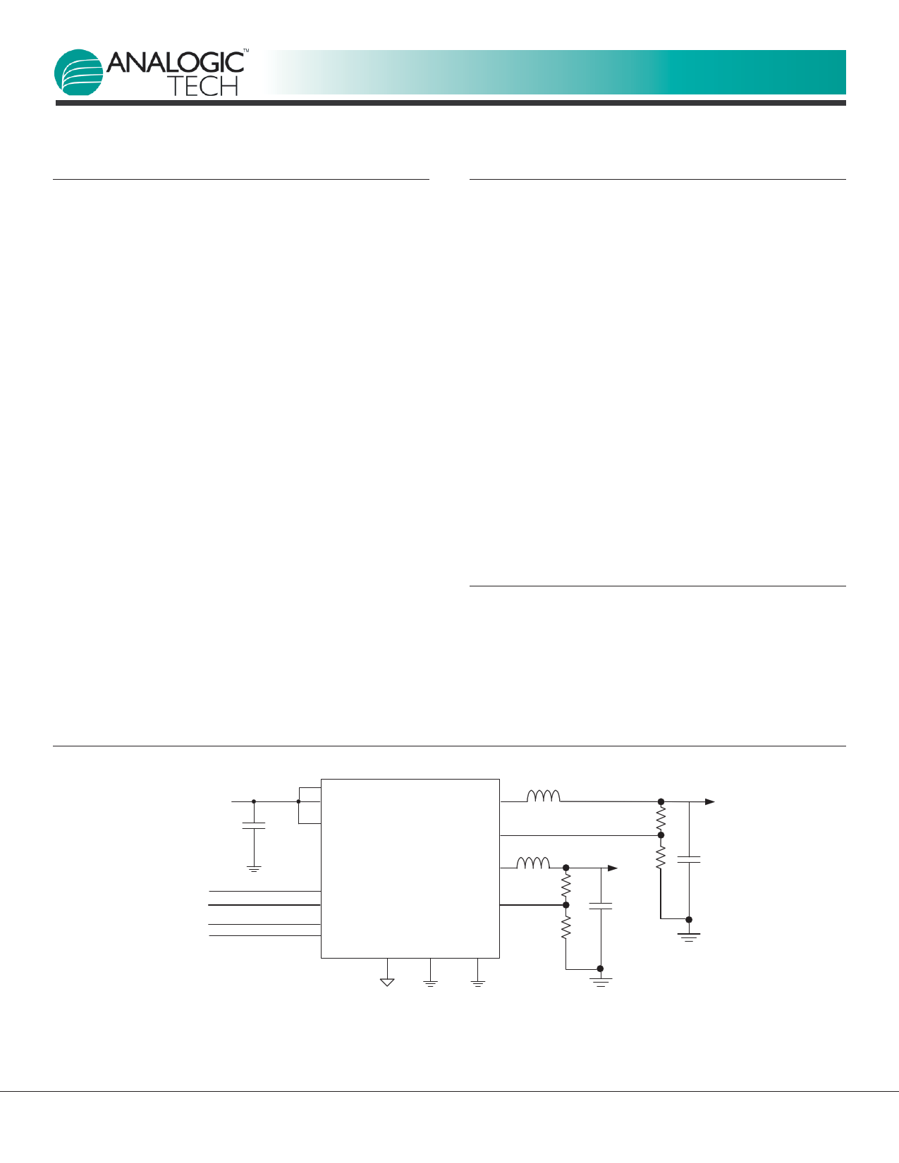
Typical Application
Input:
2.7V to 5.5V
CIN
1μF
VIN1
VIN2
LX1
VCC
FB1
AAT2713
LX2
MODE/SYNC
PS
EN1
EN2
AGND
FB2
PGND1 PGND2
L1
2.2μH
R1
L2
2.2μH
VOUT2
R2
R3
C1
4.7μF
R4
VOUT1
C2
4.7μF
2713.2008.01.1.0
www.analogictech.com
1
1 page 
SystemPowerTM
PRODUCT DATASHEET
AAT2713
Low Noise Dual 600mA Step-Down Converter with Synchronization
Electrical Characteristics
100
90
80
70
60
50
40
30
20
10
0.1
Efficiency vs. Load
(VOUT = 3.3V; L = 4.7µH; LL/PWM Mode)
VIN = 3.6V
VIN = 4.2V
VIN = 5V
VIN = 5.5V
1 10 100
Output Current (mA)
1000
Load Regulation
(VIN = 4.2V to 5.5V; VOUT = 3.3V; L = 4.7µH; LL/PWM Mode)
1.0
0.5
0.0
-0.5
-1.0
0.1
1 10 100
Output Current (mA)
1000
100
90
80
70
60
50
40
30
20
0.1
Efficiency vs. Load
(VOUT = 2.5V; L = 4.7µH; LL/PWM Mode)
VIN = 2.7V
VIN = 3.3V
VIN = 3.6V
VIN = 4.2V
VIN = 5V
VIN = 5.5V
1 10 100
Output Current (mA)
1000
Load Regulation
(VIN = 2.7V to 5.5V; VOUT = 2.5V; L = 3.3µH; LL/PWM Mode)
1.0
0.5
0.0
-0.5
-1.0
0.1
1 10 100
Output Current (mA)
1000
Efficiency vs. Load
(VOUT = 1.8V; L = 2.2µH; LL/PWM Mode)
100
90
80
70
60
50
40
30
20
10
0.1
VIN = 2.7V
VIN = 3.3V
VIN = 3.6V
VIN = 4.2V
VIN = 5V
VIN = 5.5V
1 10 100
Output Current (mA)
1000
Load Regulation
(VIN = 2.7V to 5.5V; VOUT = 1.8V; L = 2.2µH; LL/PWM Mode)
1.0
0.5
0.0
-0.5
-1.0
0.1
1 10 100
Output Current (mA)
1000
2713.2008.01.1.0
www.analogictech.com
5
5 Page 
SystemPowerTM
PRODUCT DATASHEET
AAT2713
Low Noise Dual 600mA Step-Down Converter with Synchronization
Functional Block Diagram
FB1 VCC
VIN1
EN1
AGND
MODE/SYNC
PS
FB
EN2
Err.
Amp.
Comp
Voltage
Reference
Control
Logic
Oscillator
Logic
DH
DL
Err.
Amp.
Comp.
Voltage
Reference
Control
Logic
DH
Logic
DL
LX1
PGND1
VIN2
LX2
PGND2
Functional Description
The AAT2713 is a peak current mode pulse width modu-
lated (PWM) converter with internal compensation. Each
channel has independent input, enable, feedback, and
ground pins with a 1.7MHz clock. Both converters operate
in either a fixed-frequency (PWM) mode under all load
conditions or a light load (LL) mode operation for light
loads combined with PWM mode operation for heavy
loads. The AAT2713 also produces reduced ripple and
spectral noise due to a low noise architecture. A phase
shift pin programs the converters to operate in phase or
180° out of phase. The converter can also be synchro-
nized to an external clock during PWM operation.
The input voltage range is 2.7V to 5.5V. An external
resistive divider as shown in Figure 1 programs the out-
put voltage up to the input voltage. The converter
MOSFET power stage is sized for 600mA load capability
with up to 96% efficiency. Light load efficiency is up to
90% for a 1mA load.
Soft-Start / Enable
The AAT2713 soft-start control prevents output voltage
overshoot and limits inrush current when either the input
power or the enable input is applied. When pulled low,
the enable input forces the converter into a low power
non-switching state (shutdown) with a bias current of
less than 1μA.
Low Dropout Operation
For conditions where the input voltage drops to the out-
put voltage level, the converter duty cycle increases to
100%. As the converter approaches the 100% duty
cycle, the minimum off time initially forces the high side
on time to exceed the 1.7MHz clock cycle and reduce the
effective switching frequency. Once the input drops
below the level where the converter can regulate the
output, the high side P-channel MOSFET is enabled con-
tinuously for 100% duty cycle. At 100% duty cycle the
output voltage tracks the input voltage minus the I*R
drop of the high side P-channel MOSFET.
2713.2008.01.1.0
www.analogictech.com
11
11 Page | ||
| Páginas | Total 23 Páginas | |
| PDF Descargar | [ Datasheet AAT2713.PDF ] | |
Hoja de datos destacado
| Número de pieza | Descripción | Fabricantes |
| AAT2713 | Low Noise Dual 600mA Step-Down Converter | Advanced Analogic Technologies |
| Número de pieza | Descripción | Fabricantes |
| SLA6805M | High Voltage 3 phase Motor Driver IC. |
Sanken |
| SDC1742 | 12- and 14-Bit Hybrid Synchro / Resolver-to-Digital Converters. |
Analog Devices |
|
DataSheet.es es una pagina web que funciona como un repositorio de manuales o hoja de datos de muchos de los productos más populares, |
| DataSheet.es | 2020 | Privacy Policy | Contacto | Buscar |