|
|
|
PDF XR22801 Data sheet ( Hoja de datos )
| Número de pieza | XR22801 | |
| Descripción | Hi-Speed USB to 10/100 Ethernet Bridge | |
| Fabricantes | Exar | |
| Logotipo | ||
Hay una vista previa y un enlace de descarga de XR22801 (archivo pdf) en la parte inferior de esta página. Total 30 Páginas | ||
|
No Preview Available !
XR22801
Hi-Speed USB to 10/100 Ethernet Bridge
General Description
The XR22801 is a Hi-Speed USB 2.0 compound device with an embed-
ded hub and 4 downstream USB functions: 10/100 Ethernet MAC and
PHY, UART, multi-master capable I2C controller, and an Enhanced Dedi-
cated GPIO Entity (EDGE) controller.
The upstream USB interface has an integrated USB 2.0 PHY and device
controller that is compliant with both Hi-Speed (480Mbps) and Full-Speed
(12Mbps) USB 2.0. The vendor ID, product ID, power mode, remote
wakeup support and maximum power consumption are amongst the val-
ues that can be programmed using the on-chip One-Time Programmable
(OTP) memory.
The 10/100 Ethernet MAC and PHY is compliant with IEEE 802.3 and
supports auto-negotiation, auto-MDIX, checksum offload, auto-polarity
correction in 10Base-T and remote wakeup capabilities.
The enhanced UART has a maximum data rate of 15 Mbps. Using a frac-
tional baud rate generator, any baud rate between 300 bps and 15 Mbps
can be accurately generated. In addition, the UART has a large 1024-byte
TX FIFO and RX FIFO to optimize the overall data throughput for various
applications. The automatic RS485 control feature simplifies both the
hardware and software for half-duplex RS-485 applications. If required,
the multi-drop (9-bit) mode feature further simplifies typical multi-drop
applications by enabling / disabling the UART receiver depending on the
address byte received.
The multi-master capable I2C controller and EDGE controller (up to 16
GPIOs) can be accessed via the USB HID interface. The EDGE pins or
I2C interface can be used for controlling and monitoring other peripherals.
Up to 2 EDGE pins can be configured as a PWM generator.
FEATURES
USB 2.0 Compliant Interface
10/100 Ethernet MAC and PHY
Enhanced UART
I2C Multi-master
Enhanced Dedicated GPIO Entity (EDGE)
Single +5.0V Power Supply Input
Regulated +3.3V Output Power
Single 25MHz Crystal
±15kV HBM ESD Protection on USB data
pins
±8kV HBM ESD Protection on all other pins
USB CDC-ACM, CDC-ECM and HID
compliant
Custom Software Drivers
APPLICATIONS
USB to Ethernet Dongles
POS Terminals
Test Instrumentation
Networking
Factory Automation and Process Controls
Industrial Applications
Ordering Information – Back Page
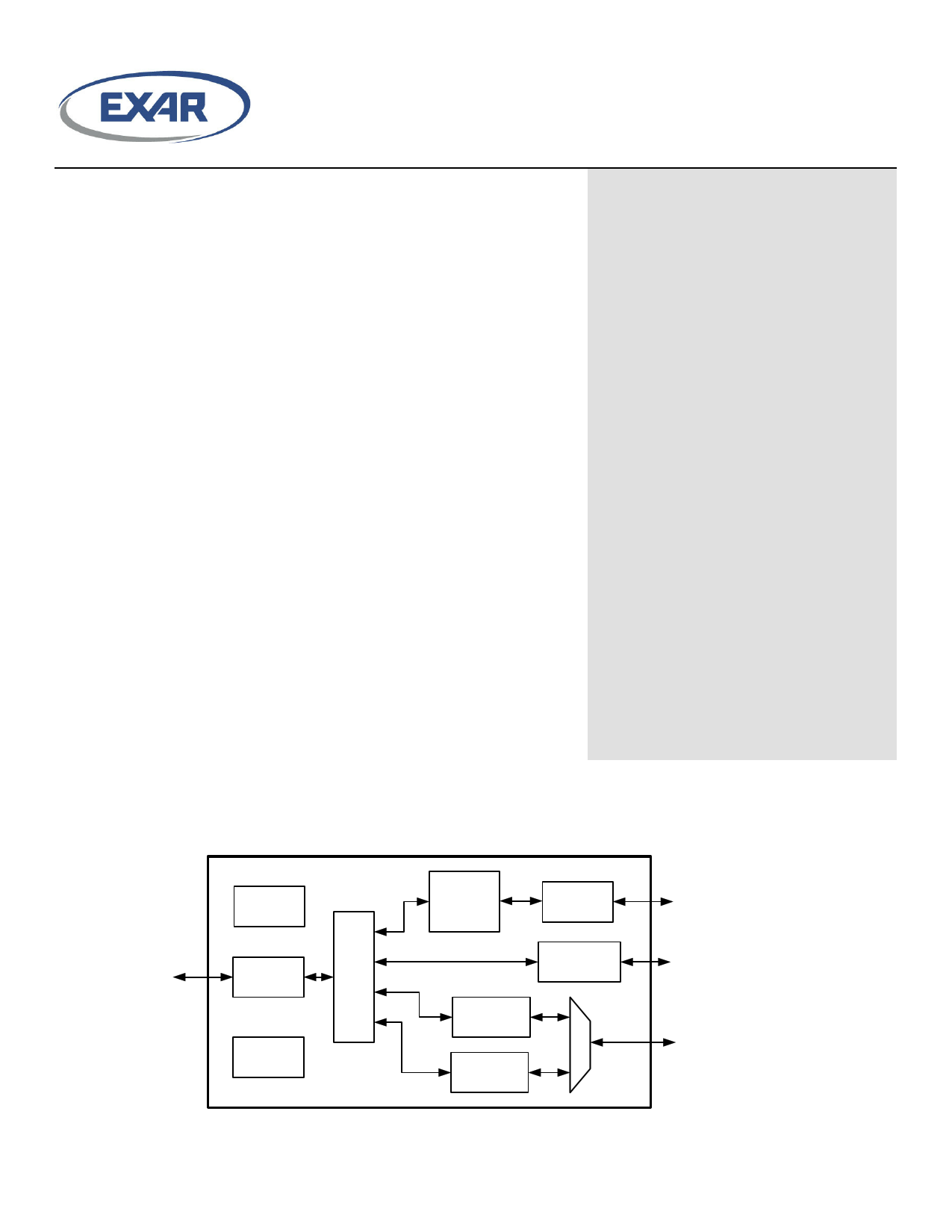
Block Diagram
USB
25 MHz
XO
Upstream
USB Phy
USB
2.0
Hub
OTP
Memory
10/100
Ethernet
Controller
Ethernet
Phy
I2C
Multimaster
UART /
Modem IO
EDGE
Controller
Ethernet
I2C
UART /
EDGE
© 2015 Exar Corporation
1 / 42
exar.com/XR22801
Rev 1B
1 page 
Pin Configuration
XR22801
VBUS_SENSE
REXT
CAP1
GND
USBD-
USBD+
VCC
ETH_SPD
1
2
3
4
5
6
7
8
Exar
XR22801
E_PAD
24 E7/TX
23 E6/RX/RWK#
22 GND
21 GND
20 CAP2
19 ETH_LINK
18 E1/CD#/G1
17 E0/RI#/RWK#/G0
Pin Assignments
Pin No.
Pin Name
1 VBUS_SENSE
2 REXT
3 CAP1
4 GND
5 USBD–
6 USBD+
7 VCC
8 ETH_SPD
9 XTALOUT
10 XTALIN
© 2015 Exar Corporation
Top View
Type
I
I
I
PWR
I/O
I/O
PWR
O
O
I
Description
VBUS Sense input. In self-powered mode, the VBUS from the USB connector needs to be
connected to this pin through a voltage divider circuit (VBUS = 5V, VBUS_SENSE = 3.3V
input) using large resistance values to minimize power. It should also be decoupled by a 0.1uF
capacitor. This feature may be enabled via the OTP whenever the hub function is configured
for self-powered mode. The VBUS_SENSE input is used to disable the pull-up resistor on the
USBD+ signal when VBUS is not present. In bus-powered mode, this pin is ignored.
Connect externally using short trace to 226 ohm 1% resistor to ground
Connect externally to CAP2 and 3V3_OUT using short trace
Power supply common, ground
USB port differential data negative
USB port differential data positive
5.0V power supply input
Ethernet 100 Mbps Speed Indicator. Asserted high for 100 Mbps.
Crystal or buffered clock output
25 MHz +/- 50 ppm Crystal or external clock input
5 / 42
exar.com/XR22801
Rev 1B
5 Page 
XR22801
host is suspended, the Ethernet Phy remains active and the XR22801 is able to both meet USB suspend mode power
requirements as well as respond to magic packet and link state changes.
The magic packet is an Ethernet packet with specific content, i.e. 6 bytes of 0xFF, followed by 16 repetitions of the target
MAC address (MAC address of the XR22801 device). This content can occur anywhere in the incoming packet payload.
The link state change will wake the USB host if the link is down when the USB host is suspended and then the link goes up,
or if the link is up when the USB host is suspended and then the link goes down.
UART
The UART can be configured via USB control transfers from the USB host. The UART transmitter and receiver sections are
described separately in the following sections. At power-up, the XR22801 will default to 9600 bps, 8 data bits, no parity bit, 1
stop bit, and no flow control. If a standard CDC-ACM driver accesses the XR22801, defaults will change. See Remote
Wakeup section on page 9.
UART transmitter
The transmitter consists of a 1024-byte TX FIFO and a Transmit Shift Register (TSR). Once a bulk-out packet has been
received and the CRC has been validated, the data bytes in that packet are written into the TX FIFO of the specified UART
channel. Data from the TX FIFO is transferred to the TSR when the TSR is idle or has completed sending the previous data
byte. The transmitter sends the start bit followed by the data bits (starting with the LSB), inserts the proper parity-bit if
enabled, and adds the stop-bit(s). The transmitter can be configured for 7 or 8 data bits with or without parity or 9 data bits
without parity. If 9 bit data is selected without wide mode, the 9th bit will always be ’0’.
UART transmitter - Wide Mode
When both 9 bit data and wide mode are enabled, two bytes of data must be written. The first byte that is loaded into the TX
FIFO are the first 8 bits (data bits 7-0) of the 9-bit data. Bit-0 of the second byte that is loaded into the TX FIFO is bit-8 of the
9-bit data. The data that is transmitted on the TX pin is as follows: start bit, 9-bit data, stop bit. Use the TX_WIDE_MODE
register to enable transmit wide mode.
UART receiver
The receiver consists of a 1024-byte RX FIFO and a Receive Shift Register (RSR). Data that is received in the RSR via the
RX pin is transferred into the RX FIFO. Data from the RX FIFO is sent to the USB host in response to a bulk-in request.
Depending on the mode, error / status information for that data character may or may not be stored in the RX FIFO with the
data.
UART receiver - Normal mode with 7 or 8-bit data
Data that is received is stored in the RX FIFO. Any parity, framing or overrun error or break status information related to the
data is discarded. Receive data format is shown in Figure 1.
UART receiver - Normal mode with 9-bit data
The first 8 bits of data received is stored in the RX FIFO. The 9th bit as well as any parity, framing or overrun error or break
status information related to the data is discarded.
7, 8 or 9-bit data
1ST byte 7 6 5 4 3 2 1 0
7 = ‘0’ in 7 bit mode
© 2015 Exar Corporation
Figure 1: UART Normal Receive Data Format with 7 or 8-bit data
11 / 42
exar.com/XR22801
Rev 1B
11 Page | ||
| Páginas | Total 30 Páginas | |
| PDF Descargar | [ Datasheet XR22801.PDF ] | |
Hoja de datos destacado
| Número de pieza | Descripción | Fabricantes |
| XR22800 | Hi-Speed USB to 10/100 Ethernet Bridge | Exar |
| XR22801 | Hi-Speed USB to 10/100 Ethernet Bridge | Exar |
| XR22802 | Hi-Speed USB to 10/100 Ethernet Bridge | Exar |
| XR22804 | Hi-Speed USB to 10/100 Ethernet Bridge | Exar |
| Número de pieza | Descripción | Fabricantes |
| SLA6805M | High Voltage 3 phase Motor Driver IC. |
Sanken |
| SDC1742 | 12- and 14-Bit Hybrid Synchro / Resolver-to-Digital Converters. |
Analog Devices |
|
DataSheet.es es una pagina web que funciona como un repositorio de manuales o hoja de datos de muchos de los productos más populares, |
| DataSheet.es | 2020 | Privacy Policy | Contacto | Buscar |